Table of Contents
Input port (usually labeled port 1)
In commercial wireless communication systems, the input port must be able to handle up to tens of watts of signal power to ensure effective coverage of long-distance signals. The input ports of directional couplers in standard communication systems are designed to withstand up to 50 watts of input power while maintaining signal attenuation below 0.5 dB to maximize signal integrity and strength.
Most home satellite reception systems use a 75-ohm impedance design, which can effectively reduce the reflection and loss of signals during transmission. When the impedance is perfectly matched, the signal loss of the system can be controlled within 1 dB, which is very necessary to ensure the quality of high definition video signals.
Directional couplers for outdoor use need to use waterproof and dust-proof materials to protect the input ports to ensure that the equipment can work stably in harsh environments. With an IP67 protected coupler, its environmental adaptability is stable over a temperature range of -20°C to +70°C.
Although the input port of copper material can improve the efficiency of signal transmission, the cost of copper is about 20%-30% higher than that of aluminum material. This increase in cost requires manufacturers to make a trade-off between performance and economic benefits.
Modern directional couplers, through the use of microelectromechanical system (MEMS) technology, can achieve smaller sizes and higher precision signal processing. Couplers using MEMS technology can reduce the port size to 1/10 of the traditional technology, while maintaining or even improving the accuracy and response speed of signal processing.
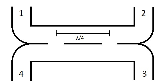
Output port (Port 2)
For directional couplers used in communication base stations, the output port needs to ensure extremely low signal loss to maintain signal coverage and quality. The output port of the high-quality communication directional coupler can control the signal loss below 0.2 dB, ensuring wireless signal transmission across several kilometers.
In medical devices, such as miniature directional couplers used in pacemakers, the output ports must ensure that the signal is accurate and stable to avoid adverse effects on heart rate regulation. According to industry standards, the signal variability of the directional coupler output port in such applications needs to be controlled within 0.1% to ensure device reliability and patient safety.
In high-end RF test equipment, the output ports of directional couplers are designed to handle frequencies up to tens of GHz. The output port in this type of device has an insertion loss of less than 0.5 dB, while the reflection loss (VSWR) is usually better than 1.05 key.
The output ports of directional couplers used in communications satellites in geosynchronous orbit need to be stable in extreme space environments (such as wide range of temperature changes and radiation levels), and the output ports of these devices can operate normally in the temperature range of -50°C to +100°C.
The output port of the directional coupler in the home theater system needs to support the transmission of multi-channel audio signals, and needs to support at least 5 or more audio channels, and the signal distortion rate of each channel needs to be controlled below 0.01% to provide the best hearing experience.
Coupling port (Port 3)
Coupling ports in directional couplers play a key role in separating part of the input signal for monitoring and controlling the energy distribution in the signal path. In the signal link monitoring of the wireless base station, the coupling port is designed to extract a small proportion of the signal (such as -20 dB) from the main signal path, so as to facilitate real-time monitoring and adjustment without affecting the main signal transmission. In order to ensure high-precision test results, the coupling accuracy of the coupling port in high-quality RF test equipment is usually controlled within ± 0.1dB.
In order to prevent interference in the signal loop in the broadcast system, the isolation degree of the coupling port is required to reach more than 30 dB. In the directional coupler used in television broadcasting stations, the high isolation of the coupling port ensures the purity and broadcast quality of the broadcast signal, which is critical to ensure that the audience receives high-quality audiovisual content.
In radar systems, coupling ports must be able to operate at high frequencies (e.g., several GHz) while maintaining low loss and high isolation performance. The coupled ports in the radar system can maintain insertion losses of less than 0.5 dB and isolation of more than 40 dB at an operating frequency of 10 GHz.
In the communication satellite system, the design of the coupling port not only needs to meet the requirements of high frequency signal processing technically, but also must be able to resist strong radiation and extreme temperature difference. The coupling port in the satellite system can operate normally in the temperature range of -60°C to +80°C, ensuring stable signal coupling.
Isolation port (Port 4)
In communication systems, especially in high-speed data transmission and precise signal processing, the performance of isolated ports is directly related to the stability and efficiency of the whole system. In optical fiber communication systems, the isolation degree of the isolated port usually needs to reach more than 35 dB to ensure that the interference of the signal between different channels is effectively suppressed.
In the test equipment, the isolation port needs to process signals with frequencies up to tens of GHz, and the design standard of its isolation is more than 40 dB to prevent signal leakage inside the device or external signal interference.
In the signal processing of the wireless base station, the efficient isolation port can reduce the energy loss, and by optimizing the signal path, reduce the overall power consumption of the system, a common wireless base station directional coupler, its isolation port insertion loss can be less than 0.3 dB, the isolation degree can be as high as 50 dB.
Isolated ports in satellite communications must be able to maintain their performance in extreme environments, such as the low temperatures and radiation conditions of outer space. Directional couplers for deep space communications with isolation ports that maintain isolation of up to 45 dB in the temperature range -80°C to +100°C.
The directional coupler used in home Wi-Fi systems, the isolation port not only improves the stability of the network, but also enhances the security of the system by reducing signal leakage, and the isolation port of this coupler is usually designed for at least 30 dB isolation.

