A waveguide antenna works by guiding high-frequency microwaves (e.g., 1-100 GHz) from a source to the radiating aperture with minimal loss. It functions as a precision transition, converting confined waveguide modes into free-space radiation, often achieving gains over 20 dBi for directional applications like radar or satellite communications.
Table of Contents
What is a Waveguide?
They are crucial in systems operating above 1 GHz, where conventional cabling becomes inefficient. For instance, a common rectangular waveguide for X-band radar (8-12 GHz) might have internal dimensions of approximately 2.29 cm by 1.02 cm (0.9 in by 0.4 in). This precise sizing is critical, as it determines the specific frequency range the waveguide can support, ensuring signals are contained and guided effectively from the source to the antenna.
| Key Characteristic | Typical Value / Description | Why It Matters |
|---|---|---|
| Common Operating Frequency | 2 GHz to 110 GHz | Defines its application range, from 5G to satellite and radar. |
| Primary Material | Aluminum or Copper | Provides high conductivity, minimizing energy loss as heat. |
| Typical Power Handling | Up to several megawatts (MW) | Crucial for high-power applications like radar pulses. |
| Signal Loss (Attenuation) | As low as 0.01 dB/meter | Vastly more efficient than coaxial cable at high frequencies. |
At its core, a waveguide is a hollow, metal tube, most often with a rectangular or circular cross-section. Its primary job is to act as a conduit for electromagnetic waves, preventing the energy from spreading out and being lost in free space. The internal dimensions of the tube are mathematically calculated to support specific propagation modes, primarily the dominant TE10 mode for rectangular guides. This mode allows a microwave signal, for example at 10 GHz, to travel through the waveguide with over 99% efficiency, far exceeding the performance of a standard coaxial cable at the same frequency, which might lose 50% or more of its power over a 10-meter run.
For a rectangular waveguide, the critical dimension is its width (a), which must be greater than half the wavelength of the signal it’s designed to carry to allow this mode of propagation. If the width is too small, the wave cannot propagate and is effectively cut off. This is why waveguides are inherently high-pass filters; they cannot carry signals below a specific cut-off frequency, which is intrinsically determined by their physical size. This makes them ideal for cleanly transporting a defined band of microwaves without interference from lower-frequency noise.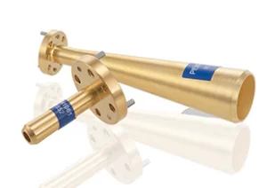
Guiding Microwaves Like a Pipe
At frequencies like 5.8 GHz or 24 GHz, commonly used for backhaul radios, signals in free space suffer from massive attenuation, losing power proportional to the square of the distance. A waveguide contains this energy, directing it along a precise path with minimal loss, often less than 0.1 dB per meter, which is crucial for maintaining a strong signal in systems like radar where power levels can be 50 kW or higher.
- Core Function: Channels high-frequency RF energy (>1 GHz) from a source (like a magnetron) to a radiating element (antenna).
- Key Advantage: Extremely low signal loss compared to coaxial cables at high frequencies, handling megawatts of peak power in radar applications.
- Physical Principle: Operates through total internal reflection of electromagnetic waves off its inner conductive walls.
The magic of a waveguide isn’t in complex electronics; it’s in its precisely engineered physical geometry. For a standard rectangular waveguide, the critical dimension is its internal width (a). This width must be greater than half the operating wavelength to allow a wave to propagate. For example, to guide a 10 GHz signal (wavelength ~3 cm), the waveguide width must be wider than ~1.5 cm. A common WR-90 waveguide has an internal width of 2.286 cm (0.9 in), making it ideal for the X-band (8.2-12.4 GHz).
The wave doesn’t simply travel straight down the middle. It propagates in a specific mode, like the dominant TE10 mode, where the electric field pattern reflects between the side walls in a half-sine wave pattern. This bouncing motion results in a phase velocity that is actually greater than the speed of light, while the group velocity (the speed of the actual signal energy) is slower.
The attenuation is remarkably low, typically in the range of 0.01 to 0.1 dB/meter, depending on the frequency and the conductive material (usually aluminum or copper). This is a 5 to 10 times improvement over the best coaxial cables at 10 GHz, which can exhibit losses of 0.5 dB/m or more. This efficiency is non-negotiable in high-power systems, where even a 1% loss translates into kilowatts of wasted energy converted into heat. The waveguide’s interior is often plated with a thin layer of ~2 to 5 microns of silver or gold to reduce surface resistance and further minimize these losses, especially in pressurized systems that prevent moisture from degrading performance.
From Waveguide to Free Space
This component is a carefully designed aperture that acts as an impedance transformer, matching the waveguide’s ~500-ohm impedance to the 377-ohm impedance of free space. A poorly designed transition can reflect over 20% of the power back towards the source, creating standing waves that can damage sensitive equipment like a $50,000 klystron amplifier. The antenna’s design directly dictates the system’s effective radiated power and coverage area.
- Primary Function: Acts as a transition element to launch guided waves into free space as radiating waves.
- Key Challenge: Matching impedances between the confined waveguide environment (~500 ohms) and free space (377 ohms) to minimize reflections.
- Performance Impact: Determines the radiation pattern, beamwidth, and efficiency of the entire microwave system.
The transition isn’t a simple hole in the pipe; it’s a precisely machined aperture or probe designed for minimal Voltage Standing Wave Ratio (VSWR), ideally below 1.2:1. This equates to a return loss of better than -20 dB, meaning less than 1% of the transmitted power is reflected back. For a high-power 100 kW radar pulse, even a 5% reflection sends 5 kW of power backwards, which can be destructive over time.
Common Types and Their Shapes
A common C-band (4-8 GHz) satellite communication antenna, for instance, uses a circular waveguide feed to support a beamwidth of 2.5 degrees for precise geostationary satellite targeting, handling signals as weak as -120 dBm. The shape dictates performance, and selecting the wrong type can degrade system efficiency by 20% or more.
| Type | Typical Frequency Range | Key Shape Characteristic | Primary Application |
|---|---|---|---|
| Pyramidal Horn | 2-18 GHz | Rectangular cross-section, linearly flared | General-purpose radiation, gain standards (15-25 dBi) |
| Circular Horn (Conical) | 8-40 GHz | Circular cross-section, conical flare | Satellite communications, omnidirectional patterns |
| Corrugated Horn | 10-30 GHz | Grooved interior surface | Low side-lobes (< -30 dB), high polarization purity |
| Open-Ended Waveguide | Varies by size | Simple, unflared rectangular or circular opening | Basic feeds, near-field testing, array elements |
Design Insight: The flare angle of a horn antenna is a critical trade-off. A wider angle (e.g., 40°) produces a broader beamwidth but introduces more phase error, reducing gain by up to 2-3 dB. A narrower angle (e.g., 15°) improves phase coherence for higher gain but results in a longer, heavier, and more expensive physical horn.
The most recognizable type is the Pyramidal Horn. It’s essentially a rectangular waveguide that flares out in both dimensions. The dimensions of the aperture (length L and width W) are calculated based on the desired gain and operating wavelength. For a 15 dBi gain horn at 10 GHz, the aperture might be approximately 12 cm by 12 cm. The gain increases roughly by 6 dB each time the aperture area doubles. This type is a workhorse for its simplicity and broadband operation, often covering a ±20% bandwidth around the center frequency.
For applications requiring symmetrical E-plane and H-plane patterns, the Conical Horn is used. Its circular cross-section is naturally suited to connect to circular waveguides, often used to propagate a rotating mode for polarization diversity. The internal diameter, for example 3.5 cm for a Ku-band (12-18 GHz) feed, determines its cut-off frequency.
Key Advantages Over Other Antennas
While a microstrip patch antenna might cost 500. This significant price difference is justified in applications where performance is non-negotiable. For instance, in a long-haul 80 GHz microwave link spanning 5 kilometers, a waveguide horn’s superior efficiency can be the difference between a stable 1 Gbps connection and a complete link failure, saving thousands of dollars in tower repeaters and maintenance over its 10-15 year operational life.
| Advantage | Waveguide Antenna Performance | Typical Competitor (Coaxial Antenna) Performance |
|---|---|---|
| Power Handling | High (MW peak, kW avg) | Low to Medium (kW peak, W avg) |
| Signal Loss (Attenuation) | Extremely Low (0.01 – 0.1 dB/m @ 10 GHz) | High (0.5 – 1.0 dB/m @ 10 GHz) |
| Operating Bandwidth | Moderate (10-20% of center freq.) | Wide (Octave or more) |
| Field Confinement | Excellent (Minimal leakage) | Good (Some leakage) |
| Durability / Environmental | High (Sealed, rigid structure) | Medium (Exposed dielectric) |
At 10 GHz, a standard coaxial cable like LMR-400 has an attenuation of approximately 0.7 dB per meter. Over a 10-meter run from the transmitter to the antenna, this results in a 7 dB loss, meaning over 80% of the transmitted power is wasted as heat. In contrast, a WR-90 rectangular waveguide at the same frequency has an attenuation of about 0.02 dB per meter. Over the same 10-meter run, the loss is a mere 0.2 dB, preserving over 95% of the power. This efficiency directly translates to higher effective radiated power (EIRP), longer range, and lower power requirements for the amplifier, reducing electricity costs by hundreds of dollars annually in a always-on system.
Typical Uses in Radar and Links
In an airport’s X-band (9.41 GHz) surface movement radar, a waveguide-fed array must reliably detect aircraft up to 5 kilometers away, 24/7, in all weather conditions, with a positional accuracy of less than 3 meters. Similarly, a long-haul 80 GHz microwave link uses a 35 dBi gain corrugated horn antenna to maintain a 99.999% annual uptime over a 5 km path, carrying over 2 Gbps of data. The high initial cost of these antennas is justified by a 15-year+ service life and near-zero maintenance, preventing millions in potential operational losses.
System Design Insight: The choice between a radar and a communication link antenna often boils down to peak vs. average power. Radar horns are built to handle megawatt pulses for microseconds, focusing on precise beam control for angular resolution of under 0.5°. Link antennas are built for continuous 1-10 watt transmission, focusing on ultra-low noise and minimal VSWR (<1.15:1) to preserve every decibel of signal integrity over decades.
1. Radar Systems (High Power, Precision Sensing):
Their ability to handle extreme peak power—often between 500 kW to 2 MW in air traffic control radars—is paramount. A single, poorly matched connector in a coaxial system would arc and fail catastrophically under this load. The waveguide and horn are a single, robust, pressurized unit that efficiently channels this energy. The precise geometry of a dual-mode or corrugated horn is used to create a specific radiation pattern with exceptionally low side lobes (< -30 dB). This is critical for distinguishing a small aircraft at a 10 km range from ground clutter. The antenna’s beamwidth, often 1.5 degrees in azimuth, directly defines the radar’s angular resolution. The entire mechanical assembly must rotate at 5-15 RPM for 24 hours a day for years, a duty cycle that demands the rigidity and durability of a waveguide-based system.
2. Point-to-Point Microwave Links (High Efficiency, Reliability):
A typical link uses a 0.6 to 1.2 meter parabolic reflector fed by a small waveguide horn. The primary metric here is link budget efficiency. A premium corrugated horn feed might have an efficiency of 70%, compared to 50% for a cheaper alternative. This 20% difference translates to a 3 dB gain improvement. Over a 30 km path at 23 GHz, this 3 dB can be the difference between a stable link with a 30 dB fade margin and an unreliable one that drops during light rain, which causes an attenuation of ~0.05 dB/km. For a telecom operator, a single link outage can cost thousands of dollars per hour in lost traffic, making the waveguide horn’s higher initial cost a wise investment. These systems are often pressurized with dry air at 5-8 PSI to prevent internal condensation that could increase VSWR by 10% and degrade the signal.
3. Satellite Communications (Low Noise, Precision):
Ground station antennas for satellite TV, data, or telemetry use large 3-10 meter dishes fed by circular waveguide horns. Here, both transmitting and receiving performance are key. On transmit, the horn must efficiently illuminate the dish. On receive, its design is critical for achieving a low system noise temperature, often below 100 K. The precision of the corrugations in a feed horn ensures high cross-polarization discrimination (> 30 dB), which is necessary to receive dual-polarized signals from a satellite 36,000 km away without interference, effectively doubling the channel capacity. The pointing accuracy of the entire system must be within 0.1 degrees to maintain a signal strength within 3 dB of its peak.


