Flexible waveguides vary primarily in material composition, frequency range, and bend radius tolerance. Corrugated copper waveguides offer low loss (0.1–0.3 dB/m) for 5–110 GHz but require ≥10x diameter bend radius, while polymer-coated helical waveguides allow tighter bends (3x diameter) with higher attenuation (0.5–1.2 dB/m). Dielectric-core flexible waveguides support 26.5–40 GHz with 0.4 dB/m loss but degrade if bent beyond 15° per 100mm. Military/aerospace applications favor copper for durability, whereas medical/robotic systems use polymer types for maneuverability. Always match waveguide type to operational flex cycles—copper lasts 50,000+ bends versus 20,000 for polymer.
Table of Contents
Shape and Bend Ability
Flexible waveguides are essential in RF and microwave systems where rigid waveguides can’t fit due to space constraints or movement requirements. The ability to bend and flex without significant signal loss is critical—most flexible waveguides can handle bend radii as low as 4x their diameter before performance degrades. For example, a 10mm diameter waveguide typically maintains low insertion loss (<0.1 dB per bend) up to a 40mm bend radius. However, tighter bends increase loss exponentially—a 20mm radius may introduce 0.3 dB loss per bend, while a 10mm radius could exceed 0.8 dB.
The maximum bend angle before permanent deformation varies by material. Copper-based waveguides tolerate up to 90° bends repeatedly, while aluminum versions may deform beyond 60°. Some high-flex designs, like corrugated stainless steel, allow 200+ bending cycles before fatigue becomes an issue.
“In high-frequency applications (18-40 GHz), even a 0.5 dB loss per bend can reduce system efficiency by 10-15%. That’s why military and aerospace specs often limit bends to 5x the waveguide diameter.”
Key Factors in Bend Performance
The inner conductor design heavily impacts flexibility. Helical corrugated waveguides, for instance, offer 30% more bend tolerance than smooth-wall types because the ridges distribute stress. A standard WR-42 waveguide (10.67mm x 4.32mm) with smooth walls may fail after 50 sharp bends, while a corrugated version lasts over 200 cycles under the same conditions.
Material thickness also plays a role. A 0.2mm-thick copper waveguide bends more easily than a 0.5mm-thick one, but the thinner wall increases vulnerability to crushing. In pressure-sensitive environments (e.g., satellite systems), waveguides with 0.3-0.4mm walls are preferred—they balance flexibility with crush resistance up to 50 psi.
Temperature affects bending limits too. At -40°C, some waveguides become 20% stiffer, increasing the risk of cracking if bent sharply. Conversely, at +85°C, copper waveguides soften, allowing tighter bends but risking permanent deformation if over-flexed.
Frequency response shifts with bending. A 26 GHz signal in a straight waveguide may see <0.05 dB loss per meter, but a single 90° bend can add 0.2-0.4 dB loss, depending on the radius. For systems operating above 30 GHz, even minor bends can cause phase shifts up to 5°, disrupting phased-array antennas.
“In telecom base stations, where waveguides often bend around structural supports, engineers keep bends ≥6x the diameter to keep VSWR below 1.2:1. Tighter bends can push it to 1.5:1, increasing reflected power by 10%.”
Real-World Tradeoffs
While thinner, more flexible waveguides are easier to install in tight spaces, they often sacrifice power handling. A standard 10mm flexible waveguide can transmit 500W at 10 GHz, but after multiple sharp bends, its max power drops to 300W due to localized heating. For high-power radar systems (e.g., 20 kW peak), rigid waveguides are still preferred—flexible versions would need active cooling to avoid overheating at bends.
The optimal bend radius depends on frequency, material, wall thickness, and environmental stress. For most commercial RF links, 6-8x diameter bends are safe, while mission-critical systems (military, space) often enforce 10x margins to ensure longevity. Always check manufacturer specs—some high-end waveguides, like those with PTFE-loaded inner layers, allow tighter bends without the usual tradeoffs.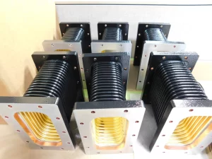
Material Choices Explained
Flexible waveguides are made from different materials, each with tradeoffs in cost, durability, and performance. Copper is the most common, offering low resistance (1.68×10⁻⁸ Ω·m), making it ideal for high-frequency signals up to 40 GHz. However, it’s 3x more expensive than aluminum and 50% heavier, which matters in aerospace applications where weight impacts fuel efficiency. Aluminum waveguides, while cheaper (50/m vs. 150/m for copper), have 40% higher resistivity (2.65×10⁻⁸ Ω·m), leading to 0.1-0.3 dB/m more loss at 18 GHz.
Stainless steel is another option, primarily used where mechanical strength is critical—like in military or industrial settings. It resists corrosion better than copper but has 5-8x higher signal loss at 10 GHz. Some hybrid designs use copper-plated steel, balancing cost and conductivity, but plating wear can increase VSWR by 10-15% over time.
“In 5G mmWave deployments (24-40 GHz), even a 0.2 dB/m loss difference between copper and aluminum can reduce cell coverage by 5-8%. That’s why carriers often pay the premium for copper in high-traffic areas.”
Key Material Properties Compared
| Material | Conductivity (MS/m) | Cost per Meter | Max Frequency (GHz) | Power Handling (kW) | Bend Cycles Before Fatigue |
|---|---|---|---|---|---|
| Copper | 58.5 | $150 | 40 | 1.5 | 500+ |
| Aluminum | 38.2 | $50 | 26 | 0.8 | 300 |
| Stainless Steel | 1.45 | $80 | 18 | 2.0 | 1000+ |
| Copper-Plated Steel | 25.0 | $90 | 30 | 1.2 | 400 |
Copper remains the best for low-loss, high-frequency applications. Its 58.5 MS/m conductivity ensures minimal attenuation—0.03 dB/m at 10 GHz, compared to 0.05 dB/m for aluminum. However, copper is soft and can deform after 500+ sharp bends, making it less ideal for moving parts.
Aluminum is lighter and cheaper, but its higher resistivity limits its use in frequencies above 26 GHz. In satellite communications, where weight is critical, aluminum waveguides are common—but engineers must account for 10-15% higher loss over long runs.
Stainless steel is the toughest, surviving 1000+ bend cycles without fatigue. It’s often used in harsh environments (saltwater, extreme temps) where corrosion resistance matters. However, its poor conductivity (1.45 MS/m) makes it unsuitable for high-frequency signals—loss exceeds 0.15 dB/m at 10 GHz.
Copper-plated steel offers a middle ground—better conductivity than aluminum but at a 20% higher cost. The plating, typically 8-12µm thick, wears down over time, increasing resistance. After 200+ flex cycles, signal loss can rise by 0.02 dB/m due to micro-cracks in the coating.
Specialized Materials for Extreme Conditions
In space applications, where thermal cycling (-150°C to +120°C) is a concern, silver-plated beryllium copper is sometimes used. It maintains stable conductivity (55 MS/m) across extreme temps, but costs $300+/m. For high-power radar (10+ kW), oxygen-free copper (OFHC) is preferred—its 99.99% purity minimizes resistive heating, allowing 2x higher power handling than standard copper.
PTFE-lined waveguides are another niche option. The lining reduces surface oxidation, extending lifespan in humid environments. However, PTFE increases insertion loss by 0.01 dB/m due to dielectric absorption.
Cost vs. Performance Tradeoffs
For budget-conscious projects, aluminum is acceptable below 18 GHz, saving $100/m over copper. But in mmWave (24-40 GHz) or high-power systems, copper’s lower loss justifies the expense. Stainless steel is only worth it if mechanical stress is the primary concern—like in robotic arms or naval radar systems.
Material choice depends on frequency, power, flex cycles, and environment. Always check manufacturer specs—some advanced alloys (e.g., CuCrZr) offer 90% of copper’s conductivity at 70% of the cost, but availability can be limited.
Best Uses for Each Type
Choosing the right flexible waveguide depends on frequency range, power requirements, environmental conditions, and budget. Copper waveguides dominate high-frequency (18-40 GHz) and low-loss applications, with 0.03 dB/m attenuation at 10 GHz, making them ideal for 5G mmWave base stations, satellite communications, and military radar. A typical 5G small cell deployment might use 10-15 meters of copper waveguide per node, costing 1,500-2,250 in materials alone, but the 3-5% better signal efficiency justifies the expense in high-traffic urban areas.
Aluminum waveguides, at 60% lower cost than copper, are common in fixed wireless access (FWA) systems and lower-frequency radar (2-18 GHz) where signal loss is less critical. A rural 5G macro site operating at 3.5 GHz might save 800-1,200 per installation by using aluminum instead of copper, with only a 0.02-0.05 dB/m penalty in performance. However, aluminum’s lower fatigue resistance (300+ bend cycles vs. 500+ for copper) makes it a poor fit for moving antenna systems or drone-based radar.
Stainless steel waveguides, while 50% more expensive than aluminum, excel in harsh environments—offshore oil rigs, naval ships, and industrial automation—where corrosion resistance and mechanical durability matter more than signal loss. A naval phased array radar might use 20-30 meters of stainless steel waveguide, accepting 0.15 dB/m loss at 8 GHz in exchange for 10+ years of saltwater exposure resistance. The 1,000+ bend cycle rating also makes stainless steel the top choice for robotic arm-mounted sensors in automotive factories, where constant movement would wear out copper or aluminum in 6-12 months.
Copper-plated steel waveguides fill a niche in cost-sensitive but performance-critical applications, like automotive radar (77 GHz) and mid-range microwave links (6-30 GHz). The 8-12µm copper layer provides 80% of pure copper’s conductivity at 40% lower cost, making it a practical choice for mass-produced ADAS systems. A 77 GHz automotive radar module might use 0.5-1 meter of copper-plated waveguide, adding 45-90 to the BOM instead of 75-150 for pure copper. However, the plating degrades after 200-300 flex cycles, so it’s avoided in steering wheel-mounted radar or retractable antennas.
For space and aerospace applications, where thermal cycling (-150°C to +120°C) and weight savings are critical, silver-plated beryllium copper or aluminum-lithium alloys are preferred. A low-Earth orbit (LEO) satellite might use 5-8 meters of silver-plated waveguide, costing 2,000-3,200, but the 55 MS/m stable conductivity across extreme temps ensures 15+ years of reliable operation. In contrast, commercial aircraft radar often uses aluminum-lithium waveguides, which are 20% lighter than standard aluminum and reduce fuel costs by 5,000-8,000 per year per plane.
In medical imaging (MRI-guided RF ablation) and scientific research (particle accelerators), oxygen-free copper (OFHC) waveguides are standard due to their 99.99% purity and ultra-low signal distortion. A 7 Tesla MRI system might require 3-5 meters of OFHC waveguide, adding 900-1,500 to the system cost, but the 0.01 dB/m loss at 128 MHz ensures precise imaging. Similarly, fusion reactor RF heating systems use OFHC or cryogenic copper waveguides to handle 10+ kW power loads with <0.05 dB/m loss at 2.45 GHz.
The cheapest option, PTFE-lined aluminum waveguides, sees use in indoor RF distribution (DAS, Wi-Fi 6E backhaul) where humidity and minor flexing are concerns. A stadium DAS installation might deploy 50-100 meters of PTFE-lined waveguide at 40-80/m, accepting 0.07 dB/m loss at 6 GHz to avoid corrosion issues in HVAC-exposed pathways. However, PTFE’s 0.01 dB/m dielectric loss makes it unsuitable for frequencies above 30 GHz.
Ultimately, the best waveguide type depends on which tradeoffs your system can tolerate. Copper wins for performance-critical, high-frequency apps, aluminum for budget-conscious fixed installations, stainless steel for extreme environments, and hybrids (copper-plated, silver-plated) for specialized needs. Always cross-check manufacturer datasheets—some newer alloys like CuCrZr offer 90% of OFHC’s performance at 70% of the cost, but availability varies by region.


