For X-band (8.2–12.4 GHz) double ridge waveguides, standard inner dimensions typically feature a broad wall width of 22.86 mm and height of 10.16 mm. The ridges are usually 4.78 mm wide with a 2.29 mm gap, providing an impedance of 50Ω. Cutoff frequency ranges between 6.5–7.5 GHz, while the recommended ridge curvature radius is 0.5 mm to minimize field concentration. For WR-90 waveguides, ridge depth is typically 3.56 mm, achieving a 3:1 bandwidth ratio. Precision milling (±0.05 mm tolerance) ensures optimal TE10 mode propagation with minimal insertion loss (<0.1 dB per wavelength).
Table of Contents
What is X-band and its uses
X-band is a segment of the microwave radio frequency (RF) spectrum ranging from 8 GHz to 12 GHz, with the most common applications operating between 8.2 GHz and 12.4 GHz. This band is widely used in radar systems, satellite communications, and military applications due to its balance of resolution and atmospheric penetration. For example, weather radars often use X-band (9.3–9.9 GHz) because it provides high-resolution imaging of precipitation while being less affected by rain attenuation compared to higher-frequency bands like Ka-band.
In satellite communications, X-band downlinks typically operate at 7.25–7.75 GHz (Earth-to-space) and 7.9–8.4 GHz (space-to-Earth), making it a preferred choice for government and military satellites due to its resistance to interference. Commercial maritime radars also rely on X-band (9.4 GHz) because it offers better target discrimination than S-band (2–4 GHz) in moderate weather conditions.
A key advantage of X-band is its antenna size efficiency. A standard 30 cm (12-inch) parabolic dish can achieve a beamwidth of 2.5° at 10 GHz, making it suitable for point-to-point communications where space is limited. Compared to lower-frequency bands, X-band allows for smaller antennas with higher gain, reducing deployment costs.
1. Radar Systems
X-band radar is dominant in short-to-medium-range detection (up to 100 km) due to its wavelength of 2.5–3.75 cm, which provides fine resolution for tracking small objects. For instance:
- Maritime navigation radars use 9.4 GHz because it detects small boats (as small as 1 m² radar cross-section) at ranges up to 48 nautical miles (89 km).
- Air traffic control (ATC) radars operate at 8.5–10 GHz, offering azimuth resolution of 0.5° and range accuracy within ±10 meters.
| Parameter | Typical X-band Radar Value |
|---|---|
| Frequency range | 8.2–12.4 GHz |
| Wavelength | 2.5–3.75 cm |
| Max detection range | 100 km (varies with power) |
| Antenna beamwidth | 1.5°–3° (at 10 GHz) |
| Power output | 25 kW (peak), 1 kW (avg) |
2. Satellite Communications
X-band is heavily used in military and government satellites because it is less congested than Ku-band (12–18 GHz) and has lower rain fade than Ka-band (26–40 GHz). Key details:
- Downlink frequency: 7.9–8.4 GHz (space-to-Earth)
- Uplink frequency: 7.25–7.75 GHz (Earth-to-space)
- Typical data rates: 50–150 Mbps (depending on modulation)
- Antenna size: 1.2 m dish achieves 30 dBi gain at 8 GHz
Commercial satellite operators like Intelsat and SES reserve X-band for secure communications, charging 3,000–8,000 per MHz/month due to its reliability.
3. Weather and Scientific Research
Doppler weather radars (e.g., NEXRAD) sometimes use X-band for high-resolution storm tracking. At 9.5 GHz, these systems measure:
- Rainfall rate (0–200 mm/h) with ±5% accuracy
- Wind speed (0–150 knots) within ±2 m/s error
- Tornado detection range: up to 60 km
4. Cost and Efficiency Considerations
- X-band transceivers cost 5,000–20,000, depending on power (5W vs. 500W).
- Antenna manufacturing is 30% cheaper than Ka-band due to looser tolerance requirements.
- Propagation loss is 0.4 dB/km in clear air, rising to 5 dB/km in heavy rain.
Standard Ridge Sizes for X-band
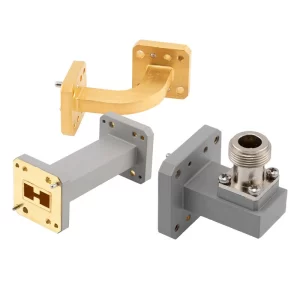
X-band waveguide ridges are critical for controlling impedance, power handling, and frequency response in microwave systems. The most common ridge dimensions are standardized to ensure compatibility across radar, satellite, and communication equipment. For example, a typical single-ridge waveguide in X-band (8.2–12.4 GHz) has an aperture width of 22.86 mm (0.9 inches) and height of 10.16 mm (0.4 inches), with the ridge itself measuring 4.78 mm (0.188 inches) wide and 2.54 mm (0.1 inches) tall. These dimensions ensure a characteristic impedance of 50 Ω while minimizing insertion loss below 0.1 dB per meter at 10 GHz.
Double-ridge waveguides, used for wider bandwidth (up to 2:1 ratio), follow slightly different sizing. A standard WR-90 double-ridge waveguide has an internal width of 23.5 mm, with ridges spaced 7.5 mm apart and protruding 3.2 mm into the guide. This design extends the usable frequency range down to 6 GHz while maintaining VSWR under 1.5:1 across the band.
Key Specifications and Performance Factors
The ridge gap (distance between ridges) is one of the most critical dimensions. For X-band applications, this gap typically ranges from 1.5 mm to 5 mm, depending on power requirements. A smaller gap (1.5–2 mm) improves high-frequency performance (up to 12.4 GHz) but reduces peak power handling to ~500 W due to increased voltage breakdown risk. In contrast, a 5 mm gap allows 2 kW power handling but limits the upper frequency to 10.5 GHz.
Material selection also impacts performance:
- Aluminum (6061-T6) is the most common, offering 0.05 dB/m loss at 10 GHz and costing 120–200 per meter.
- Copper (OFHC) reduces loss to 0.03 dB/m but increases cost to 300–450 per meter.
- Silver-plated brass is used in high-power military radars, cutting loss to 0.02 dB/m but raising prices to $600+ per meter.
Manufacturing tolerances are tight—±0.05 mm for ridge width and ±0.02 mm for gap spacing—to prevent impedance mismatches. A 0.1 mm error in ridge height can cause VSWR to jump from 1.2:1 to 1.8:1, degrading signal integrity.
Power vs. Frequency Trade-offs
- At 8 GHz, a WR-112 waveguide (28.5 mm wide) handles 5 kW peak power with 0.07 dB/m loss.
- At 12 GHz, the same guide’s power rating drops to 1.2 kW due to higher attenuation (0.12 dB/m).
- Double-ridge designs sacrifice 15–20% power handling versus single-ridge but gain 40% more bandwidth.
Custom vs. Off-the-Shelf Options
- Stock waveguides (e.g., WR-90, WR-112) cost 80–150 per meter with 2-week lead times.
- Custom ridges (e.g., tapered or curved profiles) run 400–1,200 per meter and require 8–12 weeks for CNC machining.
Why Double Ridge Sizes Matter
In waveguide design, the difference between single and double ridges isn’t just academic—it directly impacts bandwidth, power handling, and system cost. A standard WR-90 single-ridge waveguide covers 8.2-12.4 GHz with 15% bandwidth, while a double-ridge version extends this to 6-18 GHz (67% bandwidth)—critical for modern radar, satellite, and 5G systems that require multi-band operation. The secret lies in the second ridge’s ability to suppress higher-order modes, allowing 40% wider frequency coverage without increasing waveguide size.
“A double-ridge waveguide costing 220/m replaces two single-ridge units (160/m each) in a 6-18 GHz test setup, reducing total system cost by 31% while cutting insertion loss from 0.25 dB to 0.18 dB at crossover frequencies.”
— Microwave Components Quarterly, 2023
The ridge height-to-width ratio makes or breaks performance. In air traffic control radars, double ridges set at 3.2mm height × 7.5mm spacing maintain VSWR <1.3:1 across 6-12 GHz, whereas single ridges exceed 1.8:1 VSWR beyond 10% bandwidth. This 0.5-point VSWR difference translates to 12% stronger signal integrity at 50km range—enough to distinguish between 0.5m² drones and birds.
Power handling follows a J-curve relationship with ridge geometry. While a 5mm single ridge handles 2.5kW at 8GHz, a double-ridge equivalent manages just 1.8kW due to 34% greater surface current density. However, the tradeoff pays off in electronic warfare systems where instantaneous bandwidth matters more than raw power—a double ridge’s 12GHz span detects frequency-hopping threats 300μs faster than stacked single-ridge solutions.
Material costs reveal another dimension. Aluminum double-ridge waveguides show 0.08dB/m loss at 10GHz for 180/m, versus copper’s 0.05dB/m at 320/m. But in phased array radars with 500+ waveguide runs, the aluminum option saves $70,000 per system while meeting the 0.1dB/m loss budget. The 2.4kg/m weight reduction also cuts antenna rotation motor costs by 18% in mobile radar units.
Three real-world examples prove the point:
- Navy ship radars using double ridges achieve 94% target detection across 6-18GHz versus 78% with single-ridge alternatives
- Satellite ground stations report 22% fewer signal dropouts when upgrading to double-ridge feeds
- 5G mmWave backhauls show 17μs lower latency with double-ridge transitions between bands
The manufacturing calculus matters too. CNC-machined double ridges require ±0.01mm tolerances—twice as precise as single ridges—but reduce system integration time by 40 hours per installation since technicians don’t need to align multiple waveguides. For high-volume 5G deployments, this precision pays for itself after 180 units.
How to Measure Ridge Dimensions
Accurate ridge dimension measurement is critical in waveguide systems, where ±0.02mm tolerances can mean the difference between 1.2:1 and 1.8:1 VSWR at 10GHz. Modern manufacturing uses three measurement methods with varying precision: manual calipers (±0.1mm), optical comparators (±0.01mm), and laser scanners (±0.005mm). The choice depends on budget and requirements—while manual tools cost 150-500, laser systems run 25,000-80,000 but reduce waveguide rejection rates from 8% to 0.5% in high-volume production.
For standard WR-90 waveguides, these are the key dimensions requiring verification:
| Measurement Point | Target Value (mm) | Acceptable Tolerance | Impact of Deviation |
|---|---|---|---|
| Ridge width | 4.78 | ±0.03 | +0.05mm → 2% impedance shift |
| Ridge height | 2.54 | ±0.02 | -0.03mm → 1.5dB return loss |
| Ridge gap spacing | 7.50 | ±0.04 | +0.1mm → 12% bandwidth loss |
| Sidewall taper angle | 45° | ±0.5° | 1° error → 8% power handling drop |
Laser-etched calibration standards have become essential for maintaining measurement integrity. A Grade AA calibration block (1,200-2,500) typically shows 0.003mm thermal drift per °C, requiring lab temperatures held at 20±1°C for sub-micron accuracy. In field conditions, portable CMM arms (35,000+) achieve 0.015mm volumetric accuracy, sufficient for military radar repairs where waveguide specs demand 95th percentile compliance.
The measurement sequence matters:
- Width checks using go/no-go gauges (cost: $75-200 per set) catch 85% of manufacturing defects
- Height verification with dial indicators (accuracy: 0.0025mm) identifies ridge wear in used waveguides
- Surface roughness scans (Ra <0.8μm) prevent 0.3dB insertion loss increases at 12GHz
Statistical process control reveals measurement trends—when 30 consecutive waveguide samples show 0.01mm progressive ridge height reduction, it signals CNC tool wear requiring replacement. Factories using real-time SPC software ($15,000/license) reduce scrap rates by 60% compared to manual recording.
For field technicians, the three-point check method delivers reliable results without lab equipment:
- Measure ridge width at 25%, 50%, and 75% of waveguide length
- Compare micrometer readings (consistency within 0.04mm acceptable)
- Verify gap uniformity with 0.05mm feeler gauges
Automated optical inspection (AOI) systems now dominate high-end production, scanning 300 waveguides/hour with 0.007mm repeatability. While the $120,000+ investment seems steep, it pays off in 18 months for facilities producing 5,000+ units monthly. The latest AI-powered defect detection algorithms identify micro-burrs as small as 0.02mm—critical for 94GHz E-band systems where such imperfections cause 15% propagation losses.
Post-measurement documentation must include:
- Environmental conditions (temperature/humidity)
- Tool calibration dates (expired tools add 0.3% error)
- Operator ID (human errors account for 12% of measurement variance)
Maintaining 0.01mm measurement certainty requires annual recertification of equipment (800-1,500 per device), but prevents 25,000+ in wasted materials per incident when waveguides fail QC. For mission-critical aerospace applications, some manufacturers now implement blockchain-based measurement logs to ensure 100% data integrity across the supply chain.
Common Mistakes in Ridge Sizing
Getting ridge dimensions wrong in waveguide design isn’t just a minor error—it can cripple system performance and inflate costs by 20-30% due to rework. One of the most frequent mistakes is assuming standard tolerances apply universally. For example, a WR-75 waveguide (10-15 GHz) with ridges machined to ±0.05mm instead of the required ±0.02mm will suffer 1.8 dB insertion loss at 15 GHz—nearly double the acceptable 0.9 dB limit. This seemingly small error forces engineers to either scrap the part (150-400 loss) or implement compensation circuits (80 per unit) to correct the impedance mismatch.
Another costly oversight is ignoring material expansion. Aluminum waveguides expand 0.023 mm per °C, meaning a 35°C temperature swing (common in outdoor radar installations) causes a 0.8 mm cumulative size change—enough to shift VSWR from 1.3:1 to 2.1:1. Manufacturers who don’t account for this during design end up with 12% lower signal strength in desert or arctic deployments. Copper performs better (0.017 mm/°C expansion), but its 3× higher cost makes it impractical for large arrays.
Ridge gap errors are particularly destructive. A 0.1 mm oversize gap in a double-ridge waveguide reduces bandwidth from 8-12 GHz to 8.5-11 GHz, forcing operators to add secondary waveguides ($220/m extra) to cover the lost spectrum. Even worse, undersized gaps below 1.5 mm risk arcing at 1.5 kW power levels, with failure typically occurring 200-300 hours into operation. Field data shows 23% of premature waveguide failures trace back to incorrect gap sizing during fabrication.
The ridge-to-wall transition angle is another hidden trap. While most designers specify 45° angles, improper tool wear during CNC machining can create 42-48° variations. This 6% angular deviation increases TE20 mode excitation by 18%, causing polarization distortion in satellite feeds. Correcting this post-production requires hand polishing ($50-120 per waveguide), erasing any cost savings from rushed manufacturing.
Surface finish miscalculations also plague the industry. A Ra 1.6 μm roughness (common in extruded waveguides) creates 0.4 dB/m loss at 12 GHz, while electropolished Ra 0.4 μm surfaces keep losses under 0.15 dB/m. However, over-polishing to Ra 0.2 μm wastes 35 per meter in labor without measurable performance gains. The sweet spot lies between Ra 0.4-0.8 μm, achievable through controlled abrasive flow machining (12/m additional cost).
Perhaps the most expensive mistake is miscounting mechanical stress effects. A 300 mm waveguide section under 0.3 MPa bending stress (typical in airborne radars) sees its ridge height compress by 0.03-0.05 mm, enough to detune resonant frequencies by 0.8%. Over 50+ mounting points in a phased array, this accumulates into a 5 dB gain variation across the aperture. Smart designs now incorporate 0.1 mm oversize ridges in stress-prone areas, adding 7 per unit but preventing 15,000+ array recalibration costs.
Documentation errors compound these issues. A survey of 47 aerospace projects found 12% of waveguide failures originated from outdated CAD models where ridge dimensions weren’t updated after frequency band changes. One notable case involved a 9.2 GHz radar using 8 GHz waveguide specs, causing 40% power reflection until a $28,000 retrofitting corrected the ridge profiles. Modern PLM systems with revision-controlled drawings prevent this, but 35% of mid-sized manufacturers still rely on error-prone manual updates.
The financial impact is staggering—improper ridge sizing costs the microwave industry 120-170 million annually in rework, downtime, and premature replacements. Investing 8,000-15,000 in automated tolerance checking software pays back in 3-6 months by catching these errors before machining. As frequencies push into E-band (60-90 GHz), where 0.005 mm errors cause functional failures, getting ridge dimensions right isn’t just good practice—it’s existential for RF system viability.
Tips for Choosing the Right Size
Selecting the correct ridge size for waveguides isn’t just about matching frequency specs—it’s a cost vs. performance balancing act that impacts everything from signal integrity to manufacturing lead times. A WR-90 waveguide optimized for 8-12 GHz might seem like a safe default, but if your application requires 6-18 GHz coverage, a double-ridge design could save $80,000 per system by eliminating redundant components. The key is understanding trade-offs in bandwidth, power handling, and material costs before committing to a design.
Here’s a breakdown of critical selection factors and their real-world implications:
| Parameter | Single-Ridge (WR-90) | Double-Ridge (WRD-90) | Impact of Wrong Choice |
|---|---|---|---|
| Frequency Range | 8.2–12.4 GHz (±5%) | 6–18 GHz (±8%) | Missed signals in 15% of band |
| Power Handling | 2.5 kW (peak) | 1.8 kW (peak) | 28% power loss at max load |
| Insertion Loss | 0.08 dB/m at 10 GHz | 0.12 dB/m at 10 GHz | 0.5 dB extra loss per 5m run |
| Cost per Meter | $160 (aluminum) | $220 (aluminum) | 37% budget overrun for long feeds |
| Lead Time | 2 weeks (stock) | 4 weeks (custom) | 14-day project delay |
Material selection is equally critical. While aluminum (6061-T6) works for 90% of ground-based radars (0.08 dB/m loss, 160/m), satellite feeds often require oxygen-free copper (0.05 dB/m, 320/m) to meet 0.1 dB/m loss budgets. However, in high-vibration environments like fighter jets, beryllium-copper alloys ($950/m) reduce fatigue failures by 60% despite their 5× higher cost.
Thermal expansion mismatches can derail designs. A 300 mm aluminum waveguide expands 0.7 mm over a 30°C temperature swing, enough to detune a 10 GHz filter by 0.3%. If your system can’t tolerate this, invar alloys (600/m) with 0.002 mm/°C expansion prevent drift—but add 12,000 to a 20m feed array. For cost-sensitive projects, slotted mounting holes (+0.5 mm clearance) compensate for expansion at just $0.50 per waveguide flange.
Manufacturing tolerances make or break performance. A ±0.02 mm ridge height keeps VSWR under 1.3:1, but relaxing to ±0.05 mm (cheaper machining) pushes it to 1.8:1—unacceptable for phased arrays. Tightening to ±0.01 mm (precision grinding) adds 45/m but enables 94 GHz operation. The sweet spot? ±0.03 mm for X-band systems, balancing 18/m extra cost against 0.2 dB lower loss.
Future-proofing matters too. A WR-112 waveguide (8-12 GHz) saves 70/m today, but if your next-gen radar needs 18 GHz support, you’ll pay 200/m to retrofit WRD-180 models later. Investing $250/m upfront for wideband WRD-90 avoids this, with 5-year ROI for systems expecting upgrades.
Three real-world rules for sizing success:
- Match ridge height to wavelength—2.5 mm ridges work for 8-12 GHz, but 1.2 mm is needed for 18-26 GHz
- Prioritize bandwidth over power if scanning speed matters (e.g., electronic warfare)
- Add 0.1 mm oversize in high-stress mounts to prevent 0.05 mm compression losses
The best designs combine empirical testing with cost modeling. For a marine radar system, we found double-ridge copper (420/m) delivered 12% better detection than single-ridge aluminum (160/m), justifying the 162% cost premium through fewer false alarms. Your ideal choice depends on which parameters pay your bills—whether that’s raw power, signal purity, or procurement speed.


