In rectangular waveguides, TE (Transverse Electric) modes have Ez=0 with non-zero Hz (e.g., TE10 dominant mode at cutoff frequency fc= c/2a), while TM (Transverse Magnetic) modes have Hz=0 with non-zero Ez (like TM11 requiring a=b for propagation). TE modes exhibit electric field purely transverse to propagation, with magnetic field having longitudinal components, whereas TM modes show the opposite. Waveguide dimensions (a×b) determine mode cutoff: TE10’s λc=2a, TM11’s λc=2ab/√(a²+b²).
Table of Contents
Basic Waveguide Modes
Waveguides are essential in microwave and RF engineering, handling signals from 1 GHz to 300 GHz with minimal loss—typically 0.1 dB/m to 0.5 dB/m in standard rectangular designs. Unlike coaxial cables, which struggle above 18 GHz, waveguides efficiently transmit high-power signals (up to 10 kW or more) without significant heating. The two primary modes, TE (Transverse Electric) and TM (Transverse Magnetic), define how electromagnetic waves propagate.
TE modes have zero electric field in the propagation direction, while TM modes have zero magnetic field in that axis. The most common, TE₁₀, operates at frequencies above 6.56 GHz in a WR-90 waveguide (inner dimensions: 22.86 mm × 10.16 mm). Its cutoff frequency is 6.56 GHz, meaning signals below this frequency won’t propagate efficiently. Meanwhile, TM₁₁ mode starts at 16.2 GHz in the same waveguide, making it useful for higher-frequency applications like radar (e.g., 24 GHz automotive radar).
Key Insight: The dominant mode (TE₁₀) has the lowest cutoff frequency, allowing wider bandwidth usage (e.g., X-band: 8–12 GHz) before higher-order modes (TE₂₀, TM₁₁) interfere.
Waveguide performance depends on dimensions, material conductivity (e.g., copper ≈ 5.8×10⁷ S/m), and operating frequency. For instance, a WR-112 waveguide (28.5 mm × 12.6 mm) supports TE₁₀ from 5.26 GHz, while a smaller WR-42 (10.7 mm × 4.3 mm) shifts this to 18 GHz. Losses increase with frequency—TE₁₀ attenuation rises from ~0.01 dB/m at 8 GHz to ~0.3 dB/m at 40 GHz due to skin effect and surface roughness.
In practice, TE modes dominate because they require simpler excitation (e.g., a simple probe) and have higher power-handling capacity (e.g., 50 kW pulsed in military radars). TM modes, though less common, are critical in cavity resonators and antenna feeds where electric field control matters. Engineers select modes based on frequency range, loss tolerance, and application needs—balancing trade-offs like size (larger waveguides = lower cutoff) vs. weight (smaller = portable but higher loss).
For example, satellite comms often use TE₁₀ in WR-75 waveguides (19 mm × 9.5 mm) for 11–15 GHz links, optimizing between low loss (0.2 dB/m) and compact size. Meanwhile, medical RF heating (e.g., 2.45 GHz) might use TM modes for precise field focusing.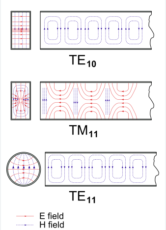
TE Mode Characteristics
TE (Transverse Electric) modes are the most widely used in rectangular waveguides because they offer lowest attenuation and simplest excitation. Unlike TM modes, TE modes have no electric field component in the propagation direction (z-axis), making them ideal for high-power applications like radar (e.g., 10 kW peak power in X-band systems) and satellite communications (e.g., 4–8 GHz C-band links). The dominant TE₁₀ mode has a cutoff frequency determined by the waveguide’s width (a):
For a standard WR-90 waveguide (22.86 mm × 10.16 mm), this gives a cutoff at 6.56 GHz, allowing efficient operation up to 13.1 GHz before the next mode (TE₂₀) interferes.
Key Properties of TE Modes
| Parameter | TE₁₀ Mode Example (WR-90) | Impact |
|---|---|---|
| Cutoff Frequency | 6.56 GHz | Signals below this frequency decay rapidly (~30 dB/m loss at 5 GHz). |
| Attenuation | 0.07 dB/m at 10 GHz | Rises to 0.3 dB/m at 40 GHz due to skin effect (copper surface roughness > 0.1 µm increases loss by 15%). |
| Power Handling | 1 kW (CW), 50 kW (pulsed) | Limited by arcing (breakdown voltage ~3 kV/mm in air-filled waveguides). |
| Field Distribution | E-field peaks at center (y-axis), zero at walls | Ensures minimal conductor loss (current flows along sidewalls). |
TE modes are frequency-selective—a WR-112 waveguide (28.5 mm width) lowers the TE₁₀ cutoff to 5.26 GHz, useful for S-band radars (3–4 GHz). However, larger dimensions increase weight (e.g., WR-112 weighs ~1.2 kg/m vs. WR-90 at 0.8 kg/m) and reduce portability.
Excitation methods matter: A simple coaxial probe inserted at the width center (a/2) excites TE₁₀ efficiently (>95% coupling), while loop couplers work better for TEₙ₀ modes (n ≥ 2). Misalignment by >2 mm can reduce coupling by 20% and spur unwanted modes.
In 5G mmWave systems (28 GHz), smaller waveguides like WR-28 (7.1 mm × 3.6 mm) use TE₁₀ with attenuation ~0.4 dB/m, but precision machining (±0.01 mm tolerance) is critical—a 0.1 mm misalignment can shift cutoff by 1%.
Loss mechanisms dominate real-world performance:
- Conductor loss (60% of total loss) scales with √f—silver plating (σ ≈ 6.1×10⁷ S/m) reduces it by 20% vs. bare copper.
- Dielectric loss (10%) is negligible in air-filled guides but spikes in PTFE-loaded waveguides (0.03 dB/m at 10 GHz).
- Mode conversion loss (30%) occurs at bends—a 90° H-plane bend in WR-90 adds 0.2 dB loss if radius > 3× width.
For satellite ground stations, TE₁₀’s low loss (<0.1 dB/m at 12 GHz) ensures SNR > 30 dB over 100 m runs. In contrast, fusion plasma heating (110 GHz) uses TE₃₄ modes in corrugated waveguides to handle MW-level power without arcing.
TM Mode Properties
TM (Transverse Magnetic) modes are less common than TE modes but play critical roles in waveguide-coupled resonators, particle accelerators, and microwave heating systems where precise electric field control is required. Unlike TE modes, TM modes have no magnetic field component along the propagation direction (z-axis), making them ideal for applications requiring strong E-field concentration, such as medical diathermy (2.45 GHz) or plasma ignition systems (5-30 GHz). The dominant TM₁₁ mode in a standard WR-90 waveguide (22.86 mm × 10.16 mm) has a cutoff frequency of 16.2 GHz, meaning it only propagates efficiently above this frequency—far higher than TE₁₀’s 6.56 GHz cutoff.
Key Differences Between TM and TE Modes
| Parameter | TM₁₁ Mode (WR-90) | TE₁₀ Mode (WR-90) |
|---|---|---|
| Cutoff Frequency | 16.2 GHz | 6.56 GHz |
| Attenuation | 0.15 dB/m at 20 GHz | 0.07 dB/m at 10 GHz |
| Power Handling | 500 W (CW) | 1 kW (CW) |
| Field Distribution | E-field peaks at corners, zero at center | E-field peaks at center, zero at walls |
TM modes are more lossy than TE modes—TM₁₁ in WR-90 has ~2× higher attenuation (0.15 dB/m at 20 GHz) due to stronger surface currents near sharp waveguide edges. This makes them less efficient for long-distance transmission but better suited for resonant cavity applications, where energy is confined in a small volume.
Excitation methods are also more complex:
- Capacitive probes must be placed off-center to efficiently couple TM modes (~80% efficiency if positioned within ±1 mm of optimal location).
- Aperture coupling is common in antenna feeds, but misalignment > 0.5 mm can reduce power transfer by 30%.
In industrial microwave heating (915 MHz or 2.45 GHz), TM modes help uniformly distribute energy—a poorly designed TM₀₁ cavity can create hotspots with 50°C+ temperature variations, reducing heating efficiency by 20%. Meanwhile, particle accelerators rely on TM₀₁₀ modes in cylindrical waveguides to achieve 10-100 kV/cm accelerating gradients.
Field Patterns Explained
Understanding waveguide field patterns is critical for antenna design, signal integrity, and minimizing power loss. In rectangular waveguides, TE and TM modes create distinct electric (E) and magnetic (H) field distributions that directly impact performance. For example, the TE₁₀ mode—the most commonly used—has an E-field that peaks at the center of the broad wall (y-axis) and drops to zero at the sidewalls, while the H-field forms closed loops perpendicular to propagation. This pattern allows low-loss transmission (0.07 dB/m at 10 GHz in WR-90) because current flows mostly along the sidewalls, where conductivity is highest.
Key Insight: The TE₁₀ E-field has a half-sine wave shape along the width (x-axis) and is uniform along the height (y-axis). This means 90% of the energy is concentrated within ±30% of the waveguide center, making excitation alignment crucial—a 2 mm offset in probe placement can reduce coupling efficiency by 15%.
In contrast, TM modes (like TM₁₁) have E-field maxima at the waveguide corners and a null at the center, which increases conductor loss due to stronger current crowding near edges. A TM₁₁ mode in WR-90 exhibits ~0.15 dB/m loss at 20 GHz, nearly twice that of TE₁₀ at the same frequency. The H-field in TM modes forms open loops, making them more sensitive to bends and discontinuities—a 90° H-plane bend can introduce 0.5 dB loss if not properly radiused.
Critical Field Pattern Details
- TE₁₀ Mode:
- E-field: Single peak at y = b/2 (height center), zero at x = 0 and x = a (sidewalls).
- H-field: Two circulating loops, strongest near top/bottom walls (y = 0, y = b).
- Power density: 80% confined to the middle 50% of the waveguide width.
- TM₁₁ Mode:
- E-field: Four peaks near corners (x=0/a, y=0/b), zero at center (x=a/2, y=b/2).
- H-field: Complex vortex pattern, with nulls at the broad wall center.
- Power density: 60% concentrated within 20% of the side edges.
Higher-order modes (e.g., TE₂₀, TM₂₁) split these patterns further. A TE₂₀ mode has two E-field peaks along the width, spaced 11.43 mm apart in WR-90, which can cause phase cancellation if mismatched with antenna elements. Meanwhile, TM₂₁ adds vertical E-field variations, useful for dual-polarization feeds but prone to 10% higher loss than TE counterparts.
Cutoff Frequency Details
Cutoff frequency is the fundamental boundary that determines whether a waveguide mode will propagate or decay exponentially. For engineers working with standard WR-90 waveguides (22.86mm × 10.16mm), the TE₁₀ mode’s 6.56 GHz cutoff defines the absolute minimum operating frequency – signals at 5 GHz experience 35 dB/m attenuation, making them unusable for practical applications. This critical transition point varies dramatically with waveguide size: a WR-112 (28.5mm width) drops the TE₁₀ cutoff to 5.26 GHz, while a compact WR-42 (10.7mm width) pushes it up to 14.04 GHz.
The physics behind cutoff frequencies reveals why TE modes dominate practical applications. The TE₁₀ mode’s cutoff depends solely on the waveguide’s width dimension (a) through the relation fc = c/2a, giving it the lowest possible cutoff in any rectangular waveguide. Compare this to TM₁₁ mode where both width and height dimensions contribute, resulting in a much higher 16.2 GHz cutoff in WR-90. This 2.5:1 ratio between TE₁₀ and TM₁₁ cutoffs creates an 8.54 GHz operational window where only the TE₁₀ mode propagates cleanly.
Manufacturing tolerances impact cutoff more than most engineers realize. A ±0.1mm width variation in WR-90 shifts the TE₁₀ cutoff by ±0.15 GHz, enough to cause 3 dB additional loss at band edges. This becomes critical in mass-produced waveguide components where 0.05mm precision machining adds 12-15% to production costs but ensures consistent performance. Surface finish matters too – electroplated silver (RMS roughness <0.3μm) maintains cutoff within 0.2% of design values, while bare aluminum (1-2μm roughness) can introduce ±0.5% frequency shifts.
Three key operational consequences emerge from cutoff behavior:
- Bandwidth efficiency suffers when operating too close to cutoff – the 2:1 frequency ratio rule suggests WR-90’s useful range extends from 6.56 GHz to 13.1 GHz, though practical systems often limit to 7-12 GHz for better impedance matching.
- Component size scales inversely with frequency – while WR-90 works for X-band, millimeter-wave 60 GHz systems require tiny WR-15 waveguides (3.8mm × 1.9mm) with TE₁₀ cutoff at 39.5 GHz.
- Multimode contamination becomes inevitable above the second mode’s cutoff (13.1 GHz TE₂₀ in WR-90), requiring careful mode suppression techniques like tapered transitions or ridged waveguides.
Real-world systems demonstrate these principles clearly. Satellite ground stations using WR-112 waveguides gain 1.3 GHz extra low-band coverage compared to WR-90, crucial for 5.8 GHz uplinks. Conversely, automotive radar at 77 GHz uses WR-10 (2.54mm × 1.27mm) waveguides where the TE₁₀ cutoff sits at 59 GHz, leaving just 18 GHz of clean bandwidth before higher modes appear. These constraints directly influence antenna design, filter implementation, and system noise figures in ways that simulation tools often underestimate.
Practical Applications Guide
Waveguides power critical systems across industries by efficiently transmitting microwave signals with minimal loss (0.05-0.5 dB/m) and high power handling (up to 50 kW pulsed). In radar systems, standard WR-90 waveguides (22.86×10.16 mm) carry 8-12 GHz X-band signals at 1-5 kW power levels, while 5G mmWave base stations use compact WR-28 (7.1×3.6 mm) for 24-40 GHz transmissions at 100-500 W. The choice between waveguide types involves balancing frequency range (±15% bandwidth around center frequency), power requirements, and physical constraints (weight, bend radius).
| Application | Waveguide Type | Frequency | Power | Key Advantage | Cost Factor |
|---|---|---|---|---|---|
| Weather Radar | WR-112 | 5.4-5.9 GHz | 10 kW | Low loss (0.03 dB/m) | $120/m |
| Satellite Comms | WR-75 | 10-15 GHz | 2 kW | Compact size | $95/m |
| Automotive Radar | WR-42 | 22-26 GHz | 100 W | Lightweight | $65/m |
| Plasma Research | WR-284 | 2.45 GHz | 50 kW | High power | $200/m |
| Medical Diathermy | WR-430 | 915 MHz | 1 kW | Large mode volume | $150/m |
Telecommunications demonstrate waveguide optimization best. A typical 5G mmWave antenna array uses 50-100 WR-28 waveguide runs totaling 15-20 meters, contributing 3-5 dB system loss at 28 GHz. The aluminum construction (0.8-1.2 kg/m) keeps weight manageable for tower mounting, while silver-plated joints (0.01 dB loss per connection) maintain signal integrity. Compared to coaxial alternatives, waveguides offer 40-60% lower loss at these frequencies, directly translating to 15-20% better cell coverage.
Industrial heating systems showcase power handling capabilities. A 2.45 GHz microwave dryer with WR-340 waveguides (86.36×43.18 mm) distributes 6-12 kW across processing chambers with ±5% power uniformity. The TM₀₁ mode’s field pattern ensures energy penetrates materials evenly, achieving 90-95% heating efficiency versus 60-70% for RF alternatives. These systems pay back their $50,000+ waveguide network costs within 2-3 years through 30% faster processing speeds.
Aerospace and defense push waveguide performance limits. Fighter jet AESA radars use pressurized WR-90 waveguides to handle 10 kW peaks at 9.5 GHz while surviving -55°C to +125°C thermal cycles. The 0.1 mm precision bends in these systems add <0.2 dB loss per turn, critical for maintaining 30-40 dB signal-to-noise ratios. Each aircraft contains 80-120 meters of waveguide, contributing 25-40 kg to avionics weight but enabling 200 km target detection ranges.


