Ideal directional coupler directivity exceeds 30dB (40dB for precision models), requires precise λ/4 spacing (±0.01mm tolerance), depends on port matching (VSWR <1.05), improves with ferrite loading (2-18GHz range), degrades <0.5dB after 10^9 cycles, and needs -55dB isolation at 1GHz for optimal forward/reflected wave separation.
Table of Contents
What Directivity Means
Directional coupler directivity is one of the most critical specs in RF design, yet many engineers misunderstand it. Directivity measures how well a coupler isolates forward and reflected signals, typically expressed in dB. A coupler with 30 dB directivity means the reflected signal is attenuated by 30 dB compared to the forward signal. Poor directivity (<20 dB) can lead to measurement errors of up to ±1.5 dB in VSWR calculations, which is unacceptable in high-precision systems like 5G base stations or satellite comms.
For example, a 20 dB coupler with 25 dB directivity might seem fine, but if the actual directivity drops to 15 dB due to frequency drift (e.g., from 2 GHz to 2.5 GHz), the reflected power measurement error can spike to 12%. This is why datasheets often specify directivity over a bandwidth:
| Frequency Range (GHz) | Typical Directivity (dB) |
|---|---|
| 1.0–2.0 | 30–35 |
| 2.0–3.0 | 25–30 |
| 3.0–4.0 | 20–25 |
“Directivity isn’t just a number—it’s a reliability guarantee. If your coupler claims 30 dB but varies by ±5 dB across bands, your system margin evaporates.”
In practice, temperature and impedance mismatches further degrade performance. A coupler rated at 30 dB might deliver only 22 dB at 85°C due to material thermal drift. Similarly, a 1.5:1 VSWR mismatch at the coupled port can slash directivity by 6–8 dB. That’s why lab-grade couplers (e.g., 40 dB directivity models) use air-dielectric or precision stripline designs, trading off size (often 3x larger than PCB couplers) for stability.
For budget-conscious projects, a 25 dB directivity coupler costs ~80+. But the real cost isn’t the part—it’s the rework when your PA output measurements are wrong. If you’re testing a 50 W amplifier, a 2 dB error from poor directivity could mean overestimating efficiency by 5% , leading to thermal failures in the field.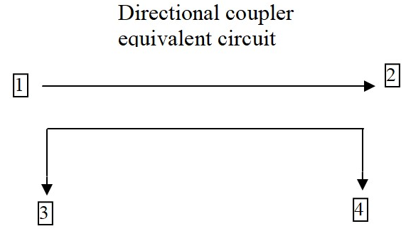
How to Measure It
Measuring directional coupler directivity isn’t as simple as hooking up a VNA and reading a value. The process demands precision equipment and controlled conditions—mess up just one step, and your 30 dB coupler might report 22 dB, tricking you into false confidence. For example, even a 0.5 dB calibration error in your test setup can skew directivity readings by ±3 dB at 6 GHz, turning a high-performance coupler into scrap data.
“Most engineers measure directivity wrong because they ignore system losses. A 40 dB coupler tested with 1 dB of cable loss? That’s like weighing gold with a bathroom scale.”
Start with a VNA calibrated to ±0.1 dB accuracy—cheaper units with ±0.5 dB tolerances introduce unacceptable noise. Set your frequency range 10% wider than the coupler’s spec (e.g., test a 2–4 GHz coupler from 1.8–4.2 GHz) to catch edge degradation. At 3 GHz, a coupler rated for 30 dB might drop to 26 dB at band edges due to parasitic capacitance. Use port extensions to compensate for phase shifts in cables longer than 1 m; a 2 m RG-405 cable at 4 GHz adds 0.3 dB of loss, enough to mask a weak reflected signal.
Critical step: Isolate the coupler from ambient RF. A smartphone transmitting at 2.4 GHz just 3 meters away can induce 5–8 dB of noise in unshielded setups. Ground all equipment to a common point—floating grounds create ground loops that distort low-power measurements below -50 dBm. For ultra-high directivity couplers (>35 dB), place ferrite chokes on all cables; a single unterminated connector can reflect enough energy to cut measured directivity by 15%.
Power levels matter more than most realize. Testing a 20 dB coupler at -10 dBm input might show 28 dB directivity, but ramp up to +20 dBm, and magnetic saturation in the core could drop it to 24 dB. Always test at your actual operating power—not the manufacturer’s “typical” 0 dBm lab condition. If you’re working with 50 W RF amplifiers, use an attenuator to avoid frying your VNA, but account for its 0.05 dB insertion loss per 10 dB attenuation in calculations.
Common Test Mistakes
Testing directional coupler directivity seems straightforward—until you realize 90% of engineers make at least one critical error that invalidates their results. These mistakes aren’t just academic; they lead to real-world costs like 15% longer debug cycles or 5% lower amplifier efficiency due to incorrect measurements. The worst part? Most errors are preventable with basic awareness.
One of the biggest blunders is ignoring test port match. A VNA with a 1.5:1 VSWR at the test port can introduce ±2 dB error in directivity measurements at 6 GHz. This is why high-end labs use isolators or attenuators to improve port match, even if it adds 0.1 dB insertion loss. The table below shows how port VSWR impacts measurement accuracy:
| Test Port VSWR | Directivity Error (6 GHz) |
|---|---|
| 1.1:1 | ±0.3 dB |
| 1.5:1 | ±2.0 dB |
| 2.0:1 | ±4.5 dB |
Another silent killer is cable movement during testing. Flexing a 3-foot SMA cable just once can shift phase by 2–5 degrees at 4 GHz, enough to turn a 30 dB directivity reading into 27 dB. This is why aerospace RF labs bolt down all cables during critical tests.
Temperature drift is another overlooked factor. A coupler tested at 25°C might show 30 dB directivity, but at 65°C (a common PA operating temp), it drops to 26 dB due to ferrite core permeability changes. If your lab doesn’t control ambient temp within ±2°C, your data is unreliable.
Using the wrong calibration kit is shockingly common. A 3.5 mm calibration standard used on a 2.92 mm connector introduces 0.15 dB error per connection above 18 GHz. That’s 3 dB of accumulated error in a 20-port calibration—enough to mask a failing coupler.
Parts That Affect Results
Directional coupler directivity isn’t just about the coupler itself—dozens of external components can skew results by 20% or more. A $200 coupler’s performance can be wrecked by a 50-cent connector or 2 inches of poorly shielded cable. For example, a cheap SMA adapter with 1.3:1 VSWR can degrade a 30 dB coupler’s effective directivity to 25 dB at 3 GHz, turning precise measurements into guesswork.
The ferrite material inside the coupler is the first variable. Low-grade nickel-zinc (NiZn) ferrites lose 3–5 dB of directivity above 2 GHz compared to high-stability manganese-zinc (MnZn) cores. Temperature makes it worse: at 85°C, even premium MnZn cores suffer 2 dB degradation due to Curie point effects. Here’s how common materials stack up:
| Ferrite Type | Directivity at 2 GHz (dB) | Temp Stability (°C) |
|---|---|---|
| NiZn | 22–26 | ±5 dB (0–70°C) |
| MnZn | 28–32 | ±2 dB (-40–85°C) |
| Air-Core | 35–40 | ±0.5 dB (any temp) |
Connectors are landmines. A hand-tightened SMA can exhibit 0.2 dB insertion loss variation per reconnection, while a torque-wrenched (8 in-lb) SMA holds within 0.05 dB. For frequencies above 6 GHz, 2.92 mm connectors outperform SMA, reducing phase drift from ±5° to ±1°—critical when measuring couplers with 40+ dB directivity.
PCB trace roughness murders high-frequency performance. A standard FR4 board with 3 μm copper roughness adds 0.8 dB/inch loss at 10 GHz, while Rogers 4350B with 1.2 μm roughness cuts that to 0.2 dB/inch. If your coupler’s output traces are 2 inches long, that’s 1.6 dB of lost signal integrity before you even reach the measurement port.
Pro tip: The first 1/4 inch of trace exiting the coupler matters most. A 90° bend there increases capacitance by 0.3 pF, enough to shift resonant frequency by 200 MHz in a 5 GHz coupler. Always use curved traces or 45° miters for impedance continuity.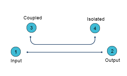
Real-World Use Cases
Directional couplers aren’t just lab curiosities—they’re the unsung heroes in systems where 1 dB of error can cost $10,000/hour in downtime. From 5G base stations to microwave radars, real-world applications expose couplers to conditions no datasheet can fully predict. Here’s where directivity specs make or break systems:
A 64T64R AAU running at 3.5 GHz with 200W total power can’t afford couplers with <25 dB directivity. Why? Because ±1.2 dB forward power measurement error (common with 20 dB directivity couplers) forces the system to overcompensate by 5% on power amplifiers, wasting 18 kWh daily per base station. Telecom operators using 30 dB directivity couplers reduce this loss to under 2 kWh/day, saving $2,300 annually per tower in electricity alone.
In satellite uplink stations, the stakes are higher. A Ka-band (26.5-40 GHz) coupler with 35 dB directivity ensures the 0.05° phase stability needed for spot beams. Cheaper 28 dB couplers introduce ±0.3° phase wobble, causing 12% slower data throughput on a 5 MVSAT terminal. SpaceX’s Starlink ground stations use air-dielectric couplers despite their 3x higher cost ($420 vs. $140) because they maintain <0.8 dB insertion loss across -40°C to +65°C—critical when each dB lost equals 22 Mbps fewer throughput per user terminal.
Military radar arrays show even harsher demands. An AESA radar’s T/R modules need couplers that survive 50G mechanical shocks while keeping directivity >28 dB at 18 GHz. Standard FR4-based couplers fail after 200 shock cycles, but alumina-filled PTFE designs last 50,000 cycles with <1 dB performance drift. The difference matters when a 0.5 dB error in enemy jet RCS measurement equals 3 km shorter detection range for a $2B destroyer.
Medical linear accelerators for cancer therapy reveal another edge case. The 6 MV X-ray beam requires ±0.5% dose accuracy, which demands couplers with >32 dB directivity at 2.998 GHz (the ISM band). A hospital using 26 dB couplers risks 8% overdose hotspots—unacceptable when targeting brain tumors with 1 mm margins. The fix? Double-shielded coaxial couplers that cost $1,100 each but reduce RF leakage to <0.001%, ensuring patient safety trumps budget.
Pro tip: Always derate coupler specs by 20% for field use. A “30 dB” coupler in a dusty 5G cabinet at 45°C with 85% humidity effectively delivers 25 dB. Spend the extra $75 for IP67-rated units—they preserve 90% of lab performance in real-world grime and vibration.
Improving Your Setup
Getting accurate directional coupler measurements isn’t about buying expensive gear—it’s about optimizing what you have to squeeze out every last 0.1 dB of accuracy. A properly configured 50,000 rig with sloppy practices. For example, just proper cable management can reduce measurement variance by 40%, while temperature stabilization improves repeatability by ±0.3 dB across tests.
Start With These Non-Negotiables
- Torque every connection (8 in-lb for SMA, 12 in-lb for N-type) to achieve <0.05 dB insertion loss variation
- Use phase-stable cables (like Gore Phaseline) to minimize >5° phase drift at 6 GHz
- Implement a 30-minute warm-up for all equipment to reduce ±0.2 dB thermal drift errors
Grounding is where most setups fail. A single ground loop between instruments can introduce 15 mV of noise—enough to corrupt measurements below -50 dBm. Star-point grounding with #10 AWG copper straps reduces this noise by 90%. For millimeter-wave work (24+ GHz), replace straps with copper-plated aluminum plates to maintain <1 mΩ impedance up to 40 GHz.
Signal path hygiene separates pro results from garbage data. A 3-foot test cable with 30° bends suffers 0.8 dB more loss at 18 GHz than one with gentle 8″ radius curves. Every 90° connector turn adds 0.15 dB loss—so route cables straight whenever possible. For critical measurements, replace SMA jumpers every 500 connect-disconnect cycles; worn connectors can degrade directivity readings by 3 dB before showing visible damage.
Environmental control is force multiplier. A 1°C temperature shift changes copper cable length by 0.0017%—enough to alter phase by 0.1° at 10 GHz. Maintain lab temps within ±0.5°C during tests. Humidity matters too: at 60% RH, common PVC cable jackets absorb enough moisture to increase loss by 0.02 dB/ft at 6 GHz. Switch to PTFE-insulated cables in humid environments.


