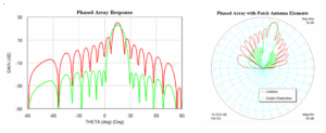
Phased Array Antenna vs Traditional | 4 Key Benefits
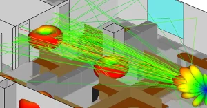
Phased array antennas have four major advantages over traditional antennas: 1. Fast beam scanning speed, up to microseconds; 2. Multi-beam capability, supporting simultaneous multi-target tracking;

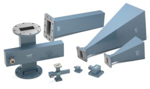
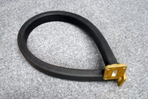
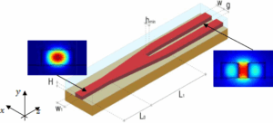
Waveguide vs Microstrip | 3 Design Considerations
Design considerations for waveguide and microstrip lines: 1. Loss: waveguide loss is less than 0.05dB/m, while microstrip loss is about 0.5dB/m. 2. Frequency response: waveguide
How to Select Waveguide Manufacturers | 5 Key Factors
Five key factors for selecting a waveguide manufacturer: 1. Precision, ensure tolerance ≤ 0.02mm; 2. Material quality, preferably high conductive alloys; 3. Cost-effectiveness, compare quotations,
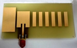
How to Reduce Costs in Antenna Fabrication | 3 Methods
Three ways to reduce antenna manufacturing costs: 1. Use PCB technology for mass production, and the cost of each piece can be reduced to less
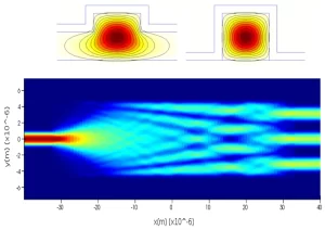
How to Optimize Waveguide Performance | 5 Pro Tips
Five tips for optimizing waveguide performance: 1. Control manufacturing tolerance (±0.005mm); 2. Select low-loss materials (such as silver-plated copper tubes); 3. Optimize the bending radius
Top 7 Custom Antenna Solutions for RF Applications
Customized antenna solutions include: 1. PCB antenna (efficiency>80%); 2. Ceramic antenna (gain about 2dBi); 3. Chip antenna (size<5x5mm); 4. Helical antenna (covering frequency 700-2700MHz); 5.
Waveguide Fabrication Process | 7 Critical Steps Explained
Waveguide production includes 7 key steps: 1. Design simulation (HFSS/CST software); 2. Material selection (such as aluminum, copper or ceramic); 3. Machining (CNC accuracy ±0.01mm);
Flexible Waveguide Manufacturers | 6 Criteria to Evaluate
Six criteria for evaluating flexible waveguide manufacturers: frequency range coverage (e.g. 2-40GHz), standing wave ratio (VSWR≤1.3), bending radius (minimum 5mm), material temperature resistance (-55℃~+125℃), insertion
Custom Waveguide Assemblies | 5 Common Mistakes to Avoid
Five common mistakes in customizing waveguide components: not selecting materials according to the frequency range (such as 2-40GHz), ignoring the standing wave ratio (VSWR>1.5), assembly

Custom Antenna Solutions | 5 Industry-Specific Applications
Customized antenna solutions are widely used in five major industries: communications (5G base station coverage increased by 30%), medical (MRI equipment signal enhanced by 25%),
Custom Antenna Design | 7 Tips for Optimal Performance
There are seven key points in custom antenna design: 1) frequency band matching (such as 2.4/5GHz dual-band); 2) gain optimization (≥8dBi); 3) low standing wave
Choosing RF Antenna Suppliers | 5 Must-Check Parameters
When selecting an RF antenna supplier, you need to examine: 1) frequency range (e.g. 2.4-5.8GHz); 2) gain (≥5dBi); 3) standing wave ratio (VSWR<1.5); 4) material
Best Practices for Waveguide Fabrication in 2025
In 2025, waveguide manufacturing will use nanoimprint lithography (±10nm accuracy), low-loss silicon nitride (≤0.1dB/cm), combined with PECVD deposition (300°C) and femtosecond laser cutting (roughness <50nm),
VSAT Antenna Cost Breakdown | 5 Factors Impacting Price 2025 Update
The cost of VSAT antennas in 2025 will be affected by five factors: 1) Antenna size, which is usually 1.2 meters to 3 meters, and
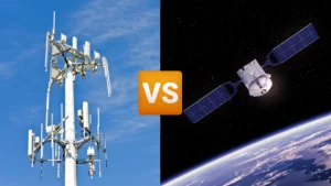
Satellite vs Cellular Antennas | 5 Performance Differences in Remote Areas
Satellite and cellular antennas perform differently in remote areas: 1) Satellites have wide coverage, reaching 99% of the world; 2) Cellular relies on base stations,
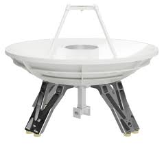
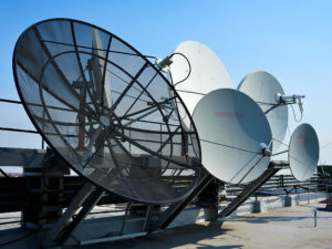
Satellite Antenna Components | 6Parts Affecting Signal Quality
There are seven major components of satellite antennas that affect signal quality: 1) reflector (gain up to 25-35dB); 2) feed source (matching impedance 30-70Ω); 3)
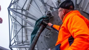
Satellite WiFi Antenna Maintenance | 5 Cleaning Tips to Prevent Signal Loss
Satellite WiFi antenna maintenance: 1) Check once a quarter and remove any snow or dust; 2) Use a soft-bristled brush to gently sweep the surface;
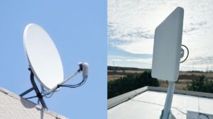
VSAT vs Satcom Antennas | 4 Differences in Range and Signal Strength
The difference between VSAT and Satcom antennas: 1) VSAT operates in the Ku or Ka band and has a high signal strength; 2) Satcom often
Satellite Antenna LNB Selection | 3 Frequency Ranges for Clear Reception
There are three frequency bands to consider when selecting a satellite antenna LNB: C-band (3.7-4.2 GHz), Ku-band (10.7-12.75 GHz), and Ka-band (18.3-31 GHz). Choose the
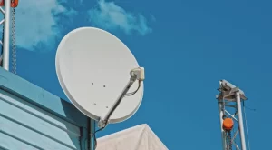
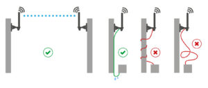
Satellite Antenna Installation | 3-Step Guide for Stable Outdoor Mounts
Three steps to install a satellite antenna: 1. Choose an open location and make sure there are no obstructions in front of the antenna. The
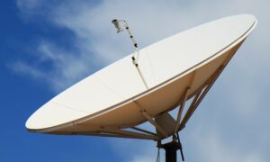
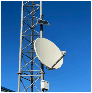
How to Choose a VSAT Antenna | 5 Key Reliable Satellite Internet
When choosing a VSAT antenna, consider: 1. Diameter, usually between 0.9 and 2.4 meters; 2. Gain level, high gain improves signal quality; 3. Frequency band


