Table of Contents
Transmission Path
At the Ku-band, 12-18 GHz; an RF rotary joint designed to operate within this frequency range should maintain an insertion loss in the range of 0.1 dB to 0.5 dB. If the insertion loss exceeds this range, there would be signal degradation that may further cause communications problems. Return loss refers to how effective the signal is being transmitted. In high-performance systems, this is usually -20 dB or better. This means less than 1% of the signal is reflected back to ensure a stable and efficient transmission path.
RF rotary joints for radar applications may be designed to handle power levels of anywhere from 100 watts to 1,000 watts, depending on operating system requirements. A typical naval radar system operating in the S-band, that is 2-4 GHz, for instance, requires an RF rotary joint that could safely transmit power up to 500 watts continuously. The cost of a rotary joint involves not just the transmission path rating, but also the price of the material used for it, wherein higher power-rated joints can go upwards of $8,000.
With the satellite tracking systems, the antenna can rotate at speeds up to 60 RPM. In such a case, there has to be a radio frequency rotary joint to ensure continuity in the signal integrity. For the common geostationary satellite dish that rotates slowly with a view to keep alignment with the satellite, the speeds of rotation may be between 10 RPM and 30 RPM depending on the design. With these speeds taken into consideration, an RF rotary joint with a rotational frequency range of up to 1 GHz would be fairly sufficient to ensure minimum insertion loss of about 0.3 dB for efficient signal transmission. The general lifetime of such a joint amounts to 50,000 hours of operation, ensuring its reliability for long-term use in satellite communications.
For deep space communication, the RF rotary joint will have larger antenna arrays transmitting through the path that must support the X-band (8-12 GHz) signals at a very low signal loss. While these systems normally can rotate at 10-20 RPM, high frequency range and large antenna diameters, sometimes greater than 30 meters, drive other requirements for the rotary joint. The RF rotary joint can be designed to meet such requirements with 2 kW power handling, less than 0.2 dB of insertion loss through 360° of rotation. Such a high-performance joint can range upwards of $15,000 or more, depending on the specifications on rotational precision and power handling capability.
Coaxial Structure
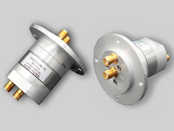
A rotary joint normally consists of an inner conductor covered by an outer conductor, normally a shield that prevents interference from entering the signal. In applications that deal with very high frequencies, such as a system operating in the Ka-band-for example, from 26.5 to 40 GHz-the inner conductor diameter is usually very small and lies mostly in the range of 0.5 mm to 2 mm to ensure the least signal loss and capability to handle high frequency. The result is that at these frequencies, small variations in the dimensions of the coaxial structure result in serious degradation of the signal; insertion loss can easily exceed 1 dB if not engineered with due care.
Material quality varies, but normally the outer conductor of the coaxial structure is manufactured from high-quality metals like aluminum or brass, which offer excellent shielding against EMI. Gold or silver plating on the outer conductor is also a common method of enhancing conductivity to help reduce signal loss in military-grade RF rotary joints used in radar systems. These do vary in cost; the pricing of silver-plated coaxial joints usually runs about 10-15% higher than the pricing of those unplated, adding roughly $500 to $1,000 to the price according to size and specifications.
The other important feature of the coaxial structure is the power-handling capability. In broadcasting applications, especially in those where the signal is broadcast at a relatively lower frequency, VHF range frequencies between 30 and 300 MHz, the coaxial structure should be capable of transmitting several kilowatts of power without overheating. It is possible to bear up to 10 kW of power for an RF rotary joint meant for 100 MHz transmission, while its insertion loss is less than 0.1 dB to prevent heating up and ensure the best transmission of a signal. They usually have larger sizes-up to 5-10 cm of outer diameter-for higher power inputs, allowing sufficient cooling.
Sliding Contacts
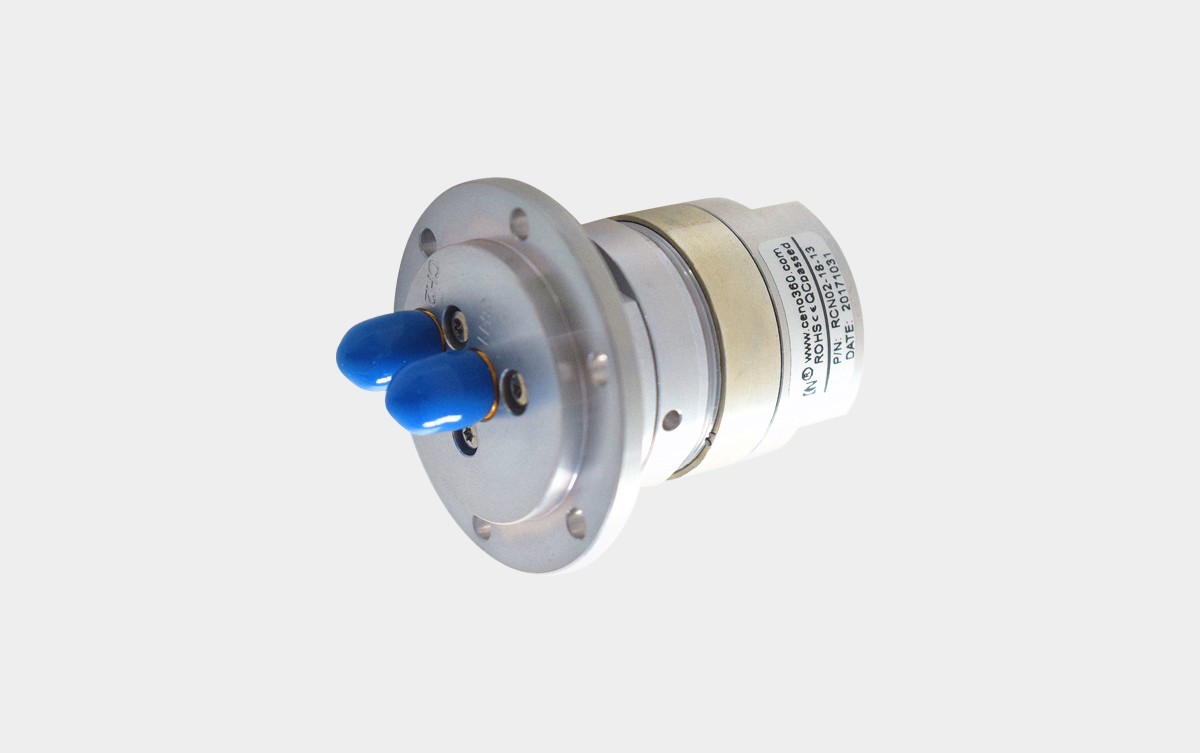
In RF rotary joints, sliding contacts are quite important; they ensure continued electrical contact during the rotation of the joint. In high-frequency applications, like the ones operating within radar systems in the frequency range of 8-12 GHz within the X-band, the design of the sliding contacts should be done in a way that the signal degradation is minimum. The insertion loss across the sliding contacts in these systems is less than 0.2 dB, pretty critical for maintaining clarity in the signal. In such a way, for a radar system with 1 kW RF transmission power, the sliding contacts shall handle the signal without increasing too much wear and resistance to assure long life and efficiency in transmission.
The material of the sliding contact is often of prime concern about performance. High-quality sliding contacts are usually made from precious metals such as gold and silver, which are highly conductive and yield very little wear. The application can, of course, affect the actual number that will be achieved, but even something as robust as gold-plated contacts can expect a relatively small lifecycle of 50,000 to 100,000 rotational cycles when compared with other materials like copper or brass, which may wear out after only 10,000 cycles. This life expectancy gap not only influences the cost of the rotary joint but, its long-term reliability as well, with gold-plated sliding contacts raising the total cost of the joint by 15-20%, or roughly $500 to $1,000.
Rotational Speed: This is where the sliding contacts must be able to sustain the system speed on rotation. If the speed of rotation for the communications system is low, in the range of 10 to 20 RPM, sliding contacts can easily provide a stable connection while the contacts experience minimal wear. Sliding contacts must be engineered to handle higher mechanical stress in a high-speed application, such as that in a rotating antenna for an airborne radar system. Rotational speeds at times will exceed 100 RPM. At these increased speeds, friction and contact wear significantly increase, and more sophisticated designs with lubricants or automatic contact adjustment mechanisms may be required. These can improve the joint’s efficiency due to lower friction losses, can add 10-15%.
Frequency Range
The range of frequency an RF rotary joint can handle is among the most critical specifications, deciding whether the joint would fit higher or lower-order applications. RF rotary joints for satellite communication systems usually deal within the Ku-band range, which falls between 12 GHz to 18 GHz. Within this high frequency, it is important to ensure that insertion loss should be as low as possible to avoid signal degradation. Generally speaking, for a well-designed RF rotary joint operating in this range, one may expect that its insertion loss does not exceed 0.5 dB, so that optimal signal strength and quality can be achieved over quite long distances of transmission.
Conversely, RF rotary joints applied in systems with frequencies lower than that, such as FM broadcasting, have much lower frequencies than those just described; thus, the frequency applied is mostly within the VHF range of 30 MHz to 300 MHz. A good example will be a rotary joint designed for 100 MHz FM transmission, and this will approximately have a much bigger diameter to accommodate the larger wavelength of frequencies applied, around 5-10 cm in diameter. The signals at these frequencies are not as prone to attenuation, and therefore, insertion loss is normally very low, often below 0.1 dB. The prices for rotary joints in lower frequency applications are generally lower, ranging from $500 to $2,000, while high-frequency units can easily be as high as $10,000 because of the difficulty in design and the precision involved.
This places even greater demands for accuracy upon the frequency in the higher-performance radar systems operating in the Ka-band frequency range, from 26.5 GHz to 40 GHz, high-end RF rotary joints are engineered to maintain losses below 0.3 dB. These systems require, in addition, return loss of -20 dB or better to ensure the least reflection of the signal, and this is less than 1% reflection of the signal back into the system. The cost of this kind of RF rotary joint is over $12,000 because of the sophisticated material required.
The frequency range has a direct impact on the amount of RF power that an RF rotary joint can handle when dealing with power handling. For frequencies at around 1 GHz, a typical rotary joint might handle up to 5 kW of RF power in many systems, a similar joint will not operate at frequencies as high as 30 GHz with more than 1 kW of power, due to increased signal loss and heating in higher frequencies.

