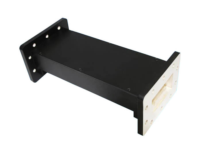
C-Band Pass Filter play an important role in microwave circuits. Working attenuation is usually used to describe the amplitude characteristics of the filter, which is divided into: low-pass, high-pass, band-pass and band-reject filters. The amplitude-frequency characteristics of the four basic types of filters are shown below.
APPLICATIONS
- Rejects terrestrial interference in C-Band (5G, Radar and C-Band transmitter)
- Easily installed between the feed and LNB
- Suitable for use with Norsat’s C-Band LNBs
- Environmentally sealed and moisture resistant (IP66)
SPECIFICATIONS
- Model: DH-40WBPF
- Frequency Range: 3.70 to 4.20 GHz
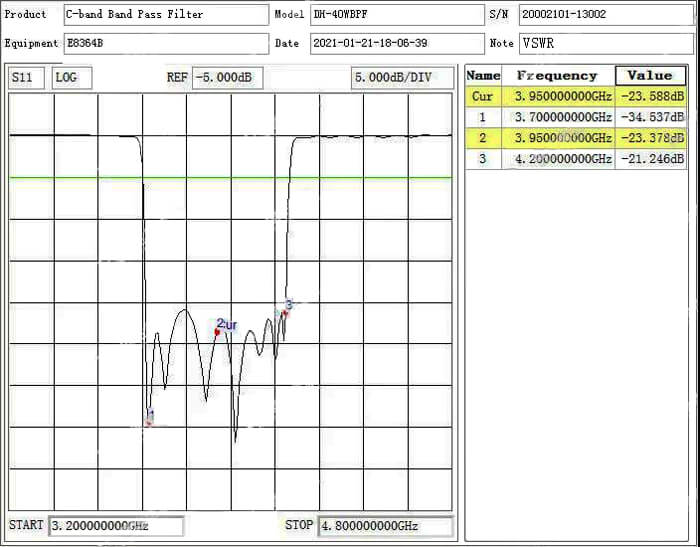
- VSWR: 1.4 : 1 max.
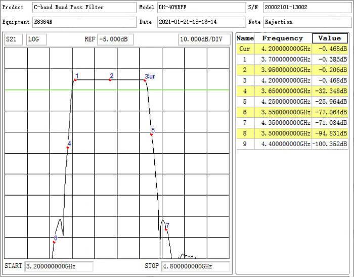
- Insertion Loss: in Band 0.5 dB max.
- Rejection: 25 dB min at 3.650 GHz and 4.250 GHz
- 60 dB min at 3.550 GHz and 4.350 GHz
- 70 dB min at 3.500 GHz and 4.400 GHz
- Group delay: variation within +/-0.5MHz 0.2nsec
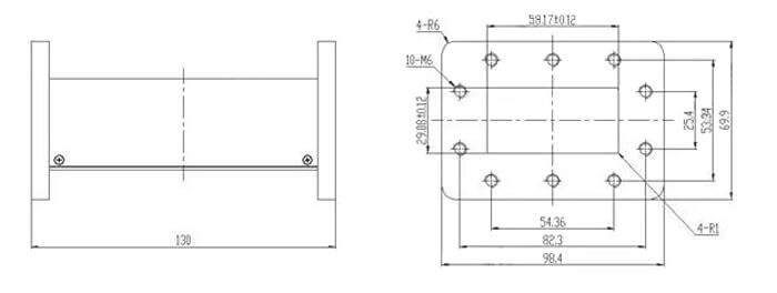
- Waveguide Flange: CPR-229G (input), CPR-229F (output)
- Dimensions (L x W x H): 130 mm x 100 mm x 70 mm
- Weight: < 650 g
TEST RESULTS
