Table of Contents
Signal Splitting
Signal splitting using coupler antennas is a fundamental technology in modern communication systems, enabling multiple devices to receive signals from a single source. In residential setups, for example, a signal splitter can distribute cable television signals to multiple rooms. High-quality splitters with a loss of only 0.5 dB ensure that the signal strength remains strong across all connections, supporting high-definition channels. In the contrast, a low-quality splitter will degrade up to 3 dB – 50% of effective signal strength, which might be the reason for the occurrence of pixelation or a signal dropout. At a rough estimate, it may cost around $80 against a $300 expense for running lines from a dedicated antenna to every television in a typical household having four televisions.
Signal splitting becomes an essential part of business and industrial operations. For example, in broadcasting stations, the coupler antennas split one output signal to feed multiple transmitters. One such antenna is able to handle an output power of 500 W per channel with a splitting ratio of 1:8, thus providing continuous service to thousands of viewers. Compared with deploying separate antennas for each transmitter, this approach reduces equipment costs by about 60% and makes maintenance easier. Moreover, it saves space because the compact design of splitters, usually 10 inches or less, minimizes the space that is required in the equipment rooms.
Signal splitting also finds its essential uses in the telecommunications industry for enhancing network coverage. Coupler antennas are often used by mobile network operators to split signals from one tower to different base stations. For example, a tower handling signals for three base stations might use a splitter with a loss of 1.2 dB, ensuring minimal degradation. This configuration can cover areas up to 20 kilometers wide, providing seamless connectivity for thousands of users. The cost savings is so huge, with just an average of $1,500 for a single splitter cost compared to $10,000 to set up additional antennas to create such coverage.
Signal Combining
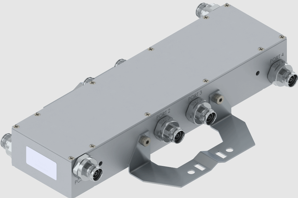
Signal combining is an important function within communication systems, allowing a number of input signals to be combined into one output for efficiency in transmission and processing. For instance, in television broadcasting, a single combiner can combine up to 16 input signals from different frequency bands into one output signal. This approach greatly minimizes the need for multiple transmission antennas, reducing infrastructure costs by up to 50%. A single high-capacity combiner costs approximately $5,000, where several antennas performing the same task can easily exceed $12,000, making the combiner a more cost-effective device.
Signal combining increases performance in wireless communication systems by allowing for MIMO systems. For instance, a 4×4 MIMO system brings together signals transmitted from four different antennas to one strong output signal, thus increasing the data throughput up to 300%. In real life, that means faster downloads, normally over 1 Gbps in 5G, for example. It reduces the cost of operation equally for the network providers by allowing the same bandwidth to cater to more users. These types of MIMO signal combiners used in typical systems can cost around US$2,500, quite cheap considering the alternative solution: increasing network coverage using more base stations.
Signal combining in industrial automation refers to the control of control signals in a system with distribution. One combiner may summarize data from sensors, actuators, and controllers operating across different machines. For example, using signal combiners for 20 robots at once in an automotive plant may provide ground for smooth and latency-free operations. Without signal combiners, synchronization would have to be maintained using a different control unit for each robot, adding over $100,000 in annual costs. Signal combiners, at about $10,000 apiece, offer an economical solution without sacrificing any degree of operational precision.
Power Monitoring
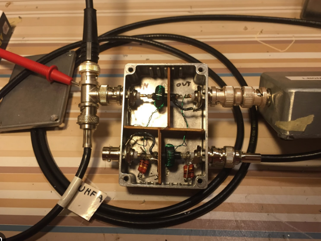
The other important application of coupler antennas is in power monitoring, where one has to measure and manage the power levels in communications and broadcasting systems accurately. A typical radio transmission system uses a coupler antenna to sample about 1% of the transmitted power so that operators can monitor outputs without interrupting the main signal flow. For example, in a system transmitting 1,000 watts, the coupler directs 10 watts to a monitoring device. This ensures that operators can verify performance and detect anomalies without adding additional equipment. High-quality monitoring setups cost approximately $3,000, while potential downtime from unmonitored systems can lead to losses exceeding $20,000 per day.
In television broadcasting, power monitoring ensures compliance with regulatory standards for transmitted signal strength. For example, broadcasters in urban areas must often limit their power output to 10 kilowatts to avoid interference with nearby stations. With coupler antennas, engineers can monitor the transmission continuously and make adjustments in the output accordingly. Such precision avoids the risk of fines, which can be in excess of $100,000 for non-compliance, and ensures that service quality remains consistent. Most modern coupler-based monitoring systems operate within an accuracy of ±0.5%, which is considerably better than older systems that operated within ±2% accuracy.
In renewable systems, like solar and wind farms, power monitoring optimizes performance. Coupler antennas in those systems measure the power of every single unit and couple it into one for analysis centrally. For instance, a wind farm with 50 turbines generating 2 megawatts each will require precise power monitoring to ensure all units work efficiently. Each coupler antenna, which costs approximately $1,200, prevents power mismatches that would cause a 5% efficiency loss, the equivalent of almost $500,000 in revenue annually for a large-scale operation.
Directional Signal Transfer
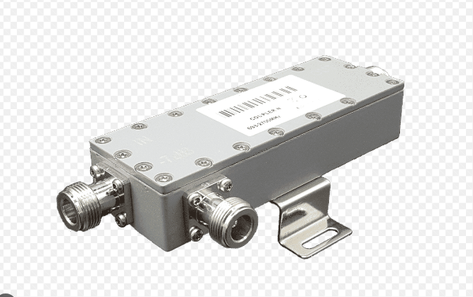
The core function of a coupler antenna is the directional transfer of signals for effective transmission to targets with minimal dissipative dispersion. In mobile communication networks, directional coupler antennas prevent interference between cell towers from one to another. For example, in a 20 dB directional coupler, 99% of the power is forwarded in the main direction while only 1% is coupled out for monitoring or other purposes. This ensures accurate signal delivery, increasing network performance and cutting operation costs. Given that a directional coupler costs about US$2,000 each, it is a cost-effective way of optimizing coverage in heavily congested urban areas, where network interference can result in losses of more than 30% in network performance.
In satellite communication, directional signal transfer ensures that signals are transmitted to and from satellites with minimal loss. A high-gain directional coupler with a gain factor of 30 dB can send out signals over distances of more than 35,000 kilometers without much degradation. This capability is quite important in satellite internet providers, where even a 1% signal loss equates to 100 Mbps of user speeds. These usually come between $10,000 and $15,000 and are vital components of satellite ground stations dealing in data for millions of users all over the world.
In radar systems, the transfer of directional signals can provide an exact detection and tracking of an object. A radar system that uses a 40 dB directional coupler can focus 99.99% of its signal strength on the target area with only a negligible side lobe effect. Such is the precision required in certain critical applications, such as air traffic control, where a very small deviation in the signal would lead to an error in the tracking of aircraft. Designed for operational safety and long life, such systems, priced over $25,000 each, can remain functional for 10 to 15 years.
Impedance Matching
The impedance matching function of the coupler antenna is very important to ensure that power is transferred with high efficiency between components in communication systems. In radio frequency systems, mismatched impedances can lead to signal reflections that may cause up to 50% or more in power losses. For example, in a 100-watt transmission system with a poorly matched impedance, up to 50 watts can be lost, reducing system efficiency by a wide margin. High-quality coupler antennas with impedance matching capabilities, typically maintaining a standing wave ratio of less than 1.2:1, cost around $500 to $2,000 and can recover these losses, improving overall system performance.
In satellite communication systems, impedance matching is crucial for maintaining signal clarity over long distances. A satellite ground station transmitting at 5 kilowatts can experience significant degradation if impedance mismatches occur. For every 1% in impedance mismatch, there is a corresponding drop of up to 2 dB in signal-to-noise ratio that can affect data transmission quality. Using advanced impedance matching in the coupler antennas minimizes such losses to less than 0.5%. Such an improvement in connectivity would mean better reliability for the end-user and less need for additional power amplification, which costs more than $10,000 per unit.
It is also an important principle in the areas of medical imaging, for instance, MRI machines. A 1.5 Tesla MRI system will be suffering from image clarity and reduced diagnostic accuracy because of impedance mismatches. The matched coupler antenna provides an assurance of good delivery of RF energy into the body of a patient at over 95% efficiency. Each of the impedance-matching couplers used in MRI systems costs in the range of $1,000 to $5,000 but ensures that multimillion-dollar imaging equipment works at its best performance, providing clear and accurate results for patients.
Frequency Filtering
Frequency filtering is one of the major functions of coupler antennas, which enables systems to isolate or amplify certain ranges of frequency for better performance. This filtering in mobile communication networks allows signals from different bands to not interfere with each other. For example, a 4G network works in the range of 700 MHz to 2.6 GHz, while a 5G network may be operating on frequencies from 3.5 GHz to 28 GHz. These ranges can be precisely isolated by using coupler antennas with bandpass filters, which can give attenuation rates of 50 dB or more for unwanted frequencies. A typical frequency filtering system for mobile networks costs roughly $5,000 per site, greatly reducing signal overlap that could result in a loss of up to 30% network efficiency.
In broadcasting, it enables stations to broadcast multiple channels with no interference. A television station with a coupler antenna and a filter that can isolate the frequencies to a 5 kHz precision can give viewers a much clearer signal. A station using 500 watts per channel on eight channels could transmit from a single antenna by using filtering to eliminate channel overlap. The cost of such a system, approximately $10,000, is considerably less than the deployment of separate antennas for each channel, which can well exceed $50,000 in infrastructure costs.
In radar systems, frequency filtering enhances detection by removing noise from all the frequency ranges except the required range. A military radar system designed to operate at 9 GHz might want to filter out interference from nearby civilian communications at 8.5 GHz. High-performance filters installed within coupler antennas can yield a suppression level of as much as 70 dB to ensure that only desired signals are processed. These kinds of systems are crucial, where clarity of signal is important-like in tracking aircraft or incoming threats-prices range between $20,000 and $30,000.
Signal Measurement
The basic use of coupler antennas is for signal measurement, which allows for the precise assessment of some key parameters: power, frequency, and signal integrity. In radio communication systems, signal measurement is important for maintaining consistent transmission quality. For example, a 1,000-watt radio transmitter might employ a coupler antenna that would send 10 watts to a monitoring device for constant analysis. In such a configuration, engineers can notice anomalies in real time and keep efficiency above 95%. The cost of one professional-grade coupler antenna with signal measurement capabilities averages $1,500, while losses due to unobserved signal issues are over $10,000 per hour for broadcasters.
In cellular networks, signal measurement is very important in regard to optimization of coverage and performance. A mobile network operator that manages 50 cell towers uses coupler antennas to measure the strength and quality of a signal at each site. Accurate measurement ensures that the towers are optimally aligned, minimizing dropped calls and therefore enhancing the user experience. With each coupler antenna costing $2,000, the deployment across the network can increase overall efficiency by up to 20%, translating into an additional revenue of up to $1 million annually for a mid-sized operator.
In satellite communication, signal measurement allows for reliable data transmission over large distances. A satellite ground station operating signals at 20 GHz has to be constantly checked to keep the signal-to-noise ratio above 30 dB. Measurement coupler antennas can detect fluctuations in power input as low as 0.1 dB and thus enable immediate correction. These systems range in price from $10,000 to $15,000 and are crucial for such applications as satellite internet, where even a small interruption affects thousands of subscribers. The precision afforded by these antennas helps maintain uptimes of 99.9%, a critical factor for service providers.

