Table of Contents
Definition
The circulator is a waveguide through which electromagnetic signals are propagated, at its ports in a specified sequence. The major area of application includes radar, communication, and satellite systems. In this respect, the device in a 10-GHz radar system will forward a signal of 1 kW to the antenna while channeling a reflected signal at only 0.1 mW back to the receiver to provide the function of the isolation of the receiver against high-power transmission signals.
For industrial microwave applications, for example, a circulator can handle power outputs to 1.5 kW with losses below 0.2%. In practical terms, that translates into economy because a circulator designed for a 15-year life can save up to $3,000 in maintenance and replacement costs compared to inferior units which may last only five years.
The circulators used in the satellite communication systems operating at Ku-band frequencies (12-18 GHz) are usually of dimension 10 cm by 10 cm and provide an isolation of more than 30 dB. By contrast, the circulators optimized to operate at 28 GHz in 5G base stations are much smaller, with dimensions of about 5 cm by 5 cm but featuring similar isolation performance.
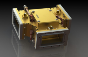
Port Configuration
A generic circulator has three ports, wherein a signal input to Port 1 goes to the output of Port 2, and that input to Port 2 gives an output to Port 3, and vice-versa. In a radar system operating at 9 GHz, for example, a three-port circulator processes a 1 kW-transmitted signal that is input via Port 1 and sends it to the antenna via Port 2, while the much weaker echo signal of approximately 0.01 W from the antenna is coupled back to Port 3 for processing in the receiver.
Applications vary with different port configurations, and three and four ports are the most commonly used circulators. For instance, a Ku-band satellite circulator, say between 12 GHz and 18 GHz, would have in excess of 30 dB isolation between ports. This will ensure that the reflected signal from the antenna does not exceed 0.001 W when the input signal power is 10 W, hence maintaining signal integrity. These four-port circulators, as they are sometimes called, are also used in chains of power amplifiers to protect the sensitive components from reflected energy. It is designed to handle powers in excess of 2 kW, up to 0.5% reflection losses.
Physical arrangements of the ports could be influential in the performance and the size of the circulator. The compact circulators in 5G base stations at millimeter-wave frequencies – for example, 28 GHz – are designed by putting the ports close together, within a 5cm × 5cm package. The circulators at 2.45 GHz for industrial microwave applications are the largest; these have spacings between the ports up to 15-20 centimeters to handle very high-power levels such as 10 kW.
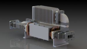
Material Composition
The general application of ferrite material with unique magnetic properties allows one-way flow of the signals, and for that, they are usually used. For example, a typical high-quality ferrite circulator in systems operating at 10 GHz has the power-handling capacity up to 2 kW and insertion loss not exceeding 0.2 dB to ensure that main parts of energy could be transmitted.
In fact, many circulators used for industrial work at 2.45 GHz use 5 mm thick ferrite discs of the density of 4.8 g/cm³. These specifications also enable high-power handling for many devices operating at more than 10 kW of continuous power at an isolation level above 35 dB. That indeed minimizes energy dissipation due to signal flow in an undesired direction and thus lowers the actual consumption of input energy up to 15%.
The good quality ones work within a wide range of temperatures-from -40°C to 100°C-without severe degradation of the performance. For example, circulators operating in satellite communications must maintain the same level of isolation and insertion loss for temperatures within this range to operate effectively. These circulators are typically rated to operate in space for more than 15 years-about 130,000 hours-without a replacement, thereby avoiding the need for multiple replacements and reducing overall mission costs by millions of dollars.
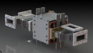
Operating Principle
A waveguide circulator works on the principle of routing electromagnetic waves in a particular sequence through its ports. The ferrite at the center of the waveguide creates a magnetic field that causes the rotation of the signals due to the Faraday effect. As a result, for instance, when a circulator operates at 10 GHz, it changes the phase of the signal in such a way that a wave injected into Port 1 is emitted purely from Port 2 with only less than 0.2 dB insertion loss while the isolation exceeds 30 dB.
The ferrite has a disc shape with a diameter around 15 mm for operation in the X-band (8 to 12 GHz) in its usual three-port version. The magnetic field strength for optimum operation is about 0.3 Tesla. In a satellite communication system, for instance, this amount of isolation prevents reflected power below 0.001 W from interfering with the 10 W transmitted signal, hence improving clarity and signal reliability.
In fact, for higher frequencies-for example, 28 GHz, which is one frequency band in 5G-a small device size is used with 5 mm in diameter and a high magnetic field strength of 0.5 Tesla. The typical value of the efficiency of the 28 GHz circulator in the base station in 5G is usually as high as 98%, providing good reliability and high-speed data transmission to the end users.
Frequency Range
Waveguide circulators operate within a well-defined range; for example, the X-band 8-12 GHz for radar applications or the Ka-band 26.5 to 40 GHz for satellites. For instance, one such X-band circulator used for marine radar systems has an operating frequency range from 9.3 GHz up to 9.5 GHz and can well direct the signal with isolation levels more than 30 dB and less than 0.3 dB insertion loss.
The circulators, which have been applied in a low frequency band, that is L-band, operating in a frequency range of 1-2 GHz, find application in GPS and air traffic control. The design of the L-band circulators has wider bandwidth, typically ranging from 1.2 GHz to 1.6 GHz. Their physical dimensions are larger in size, because of longer wavelengths, such as 20-30 mm diameter ferrite discs.
Higher frequency parts of the microwave frequency spectrum, such as the Ka-band (26.5-40 GHz), are increasingly being utilized in newer applications such as 5G telecommunications and high-speed satellite internet. Applications for these circulators have been developed with compact sizes down to 5 mm diameter and must be tuned very precisely to minimize losses.
Applications in Systems
In radar systems, circulators are used to separate the transmitted and received signals, allowing a single antenna to be used. For example, in X-band radar operating at 9 GHz, a circulator directs a 1 kW transmission to the antenna and ensures the reflected signal of only 0.1 mW is sent to the receiver. This isolation prevents high-power transmission signals from affecting sensitive receiver components, thus it enhances system reliability and reduces operating costs up to 20%.
Ka-band circulators work in the frequency range from 26.5 GHz to 40 GHz, while ensuring more than 30 dB isolation to prevent the reflected signal from the satellite antenna to be fed back into a transmit chain. These circulators operate up to 50 W power in compact satellite transceivers. The performance of these circulators is optimized within this limited space and their lifetime is more than 15 years approximating 130,000 hours of operation.
These circulators operate within the millimeter-wave spectrum at frequencies such as 28 GHz, with very low signal loss due to insertion losses commonly below 0.5 dB. This is why a single 5G base station circulator can support data throughput over 1 Gbps with very low noise, hence assuring several thousand users of seamless connectivity simultaneously.
Power Handling
Many Radar circulators with a 10 GHz can operate at power peaks up to 1 kW and dissipate low insertion loss during transmission under 0.2 dB. These also safeguard the sensitive stages of the receivers in reflective high powers and give, at an approximated calculation of reliability within the time frame of operation to be up to 10 yrs at least, a maintenance reduction cost up to 20% to systems in use.
In microwave heating systems at 2.45 GHz, circulators can handle continuous power outputs to 10 kW. Such a device is crucial to allow energy to proceed to the heating chamber while safely returning reflected power back to the generator. In many instances, better energy efficiency-often as high as 90%-may translate into savings of several thousand dollars a year for large processing plants.
The Ka-band circulator operates within the range from 26.5 to 40 GHz to pass on power up to 50 W in a very compact satellite transceiver system. These are with an insertion loss below 0.5 dB and thereby provide minimal degradation to an RF signal during passing it through. This capability enables data transport for satellite internet users that is continuous, with throughput beyond 100 Mbps.

