Table of Contents
Shape and size
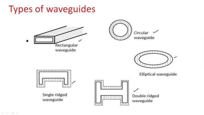
The core design parameters of a rectangular waveguide include width and height, which directly determine the cutoff frequency of the waveguide and the type of mode it can support. The internal dimensions of a common rectangular waveguide are 22 mm wide and 10 mm high, which makes the basic transmission mode of the waveguide TE10 and the cutoff frequency about 6.56 GHz.
In ground-based radar systems, waveguides of larger sizes (e.g. 72 mm width, 34 mm height) are needed to accommodate the transmission requirements of lower frequency bands (e.g. L-band, 1-2 GHz). This larger waveguide is capable of handling higher power outputs and is often used in radar systems that require wide coverage and far-reaching detection.
Although larger waveguides can provide lower cutoff frequency and higher power capacity, they use more material and cost more to process. Compared to small waveguides with dimensions of 10 mm × 5 mm, large waveguides of 72 mm × 34 mm can be 3 to 5 times higher in material cost. In satellite communications, a medium-sized waveguide with a size of 15 mm × 8 mm is usually used, which can ensure performance while minimizing space consumption to ensure a compact layout of the device.
Increasing the width of the waveguide can reduce its cutoff frequency and expand the range of frequencies that can be used, but it may also increase the transmission loss per unit length. A waveguide whose width increases from 10 mm to 30 mm can reduce its cutoff frequency from about 10 GHz to about 3.3 GHz, but the transmission loss may also increase from 0.1 dB per meter to 0.3 dB per meter.

Operation mode
Rectangular waveguides support several modes of operation, the most common of which are transverse electric (TE) mode and transverse magnetic (TM) mode. The basic TE10 mode is the lowest propagatable mode in a rectangular waveguide, and the electric field component vibrates only in the width direction of the waveguide. For a standard waveguide with an internal dimension of 22 mm x 10 mm, the TE10 mode has a cutoff frequency of about 6.56 GHz. The TE20 mode is a mode that propagates at frequencies higher than twice the cutoff frequency of the TE10 mode, which has a cutoff frequency of 13.12 GHz for the same size waveguide.
When designing a system with specific frequency band requirements, it is necessary to ensure that the size of the waveguide matches the selected mode to avoid unnecessary mode aliasing and signal loss. For a communication system that is required to operate above 10 GHz, a waveguide is chosen to prefertively transmit TE20 or higher modes to ensure signal clarity and system stability.
The use of highly conductive materials such as copper or aluminum can reduce the loss of electromagnetic waves inside the waveguide, thereby supporting clearer mode transmission. Copper waveguides may have lower loss rate than aluminum waveguides when transmitting TE10 mode. For operation in a lower frequency range, the size of the waveguide can be increased to reduce the cutoff frequency of the basic mode and increase the number of modes that can be supported. Conversely, if high-frequency operation is required and space is limited, the waveguide size can be reduced to focus on a few efficient transmission modes.
Cut-off frequency
The common rectangular waveguide size has a width of 22 mm and a height of 10 mm, and the cutoff frequency calculation formula of its basic transmission mode TE10 is fc=c2af_c = \frac{c}{2a}fc =2ac, where ccc is the speed of light and aaa is the width of the waveguide. For this waveguide, the TE10 mode has a cutoff frequency of about 6.56 GHz.
The cutoff frequency is inversely proportional to the size of the waveguide, with the width of the waveguide increasing from 22 mm to 44 mm, and the cutoff frequency of the TE10 mode will be halved, from 6.56 GHz to 3.28 GHz. A system needs to operate between 8 GHz and 12 GHz, and it is necessary to select a waveguide with a cutoff frequency below 8 GHz.
In the 22 mm × 10 mm waveguide described above, the second transmission mode, TE20, has a cutoff frequency twice that of the TE10 mode, about 13.12 GHz. The use of highly conductive materials such as copper or silver can reduce internal losses.
bandwidth
The bandwidth of a rectangular waveguide refers to the frequency range in which it can effectively transmit electromagnetic waves, depending on the waveguide cutoff frequency and design parameters. A rectangular waveguide with a width of 22 mm has a cutoff frequency of approximately 6.56 GHz for the TE10 mode. If the waveguide is designed to operate in the 10 GHz to 15 GHz band, then its bandwidth is 5 GHz.
By widening the width of the waveguide, the cutoff frequency can be reduced and the frequency range of its operation can be expanded. For a waveguide increasing from 22 mm to 44 mm width, the TE10 cutoff frequency can be reduced from 6.56 GHz to 3.28 GHz.
Low loss
A standard 22 mm × 10 mm rectangular waveguide has a transmission loss of about 0.1 dB/m at a frequency of 10 GHz. At the same 10 GHz frequency, the loss of copper waveguide may be only 0.05 dB/m, compared to the 0.1 dB/m loss of aluminum.
The larger waveguide size can reduce the cutoff frequency, increasing the waveguide width from 10 mm to 20 mm, can reduce the cutoff frequency of the TE10 mode from 10 GHz to 5 GHz, and the loss is also reduced from 0.1 dB/m to 0.07 dB/m due to the reduced frequency. In ultra-high frequency (such as above 30 GHz) applications, even small material defects or inhomogeneity can significantly increase the loss, which can increase to 0.3 dB/m for waveguides at 30 GHz.

