A waveguide magic tee functions by splitting or combining microwave signals with minimal loss. It features four ports: two collinear and two side (difference) ports. Signals entering one collinear port split equally between the side ports without affecting the opposite collinear port, due to orthogonal field orientations. This enables isolation greater than 30 dB between the collinear ports. Proper impedance matching ensures optimal performance, typically maintaining a VSWR below 1.2.
Table of Contents
Operating Principle of Magic Tee
At 3 a.m. that day, a certain satellite control center suddenly received an alert for a 1.8dB drop in EIRP value—there was a problem with the Ku-band transponder of Zhongxing-16. The engineers rushed to the waveguide test bench with a Keysight N5245B network analyzer and eventually found abnormal reflections in the H-arm of the magic tee (Magic Tee). This thing looks like a metal cross, but to make the four ports behave properly, the complexity inside is even more intricate than the proton unfolding in “The Three-Body Problem.”
A magic tee is essentially a three-dimensional microwave signpost (3D Microwave Router). When a 30GHz signal rushes in from the E-arm (parallel arm), the electric field splits like it has been cut by a knife: half goes up to the H-arm, and the other half heads straight to the side arm. The key here lies in those few mode conversion steps (Mode Transition Steps) inside the waveguide—they act as traffic police, ensuring that TE10 mode transitions into TE20 mode without causing a “traffic accident.”
- ▎Military-grade precision: According to MIL-PRF-55342G Section 4.3.2.1, the phase deviation of the four ports must be ≤2° (measured at 1.7°@28GHz).
- ▎Power distribution trick: The dielectric matching block (Dielectric Matching Block) connected to the side arm is not just decoration—it can absorb 0.15dB of reflection loss.
- ▎Vacuum environment test: Spaceborne versions must undergo 240 hours of burn-in at 10^-6 Torr vacuum to ensure that the silver plating does not blister.
Last year, ESA’s Galileo satellite tripped up. After three years of in-orbit operation, the voltage standing wave ratio (VSWR) of the H-arm suddenly soared from 1.25 to 2.1, directly causing the satellite’s positioning error to exceed the standard. Post-mortem disassembly revealed that a screw torque was short by 0.3N·m, causing millimeter-level deformation—at 94GHz, this error is equivalent to performing an amputation on an ant with nail clippers.
Microwave engineers know the power of Brewster angle incidence (Brewster Angle Incidence). The 45-degree slanted surface of the magic tee’s side arm is not arbitrarily cut; it requires 200 iterations of calculations with Ansys HFSS to ensure that reflected and incident waves form perfect destructive interference in the E-plane. A certain research institute once took a shortcut using generic CAD modeling, resulting in a ghost signal -23dBc measured at the 26.5GHz frequency point, almost turning the radar into a “blind eye.”
Nowadays, military-grade magic tees are starting to incorporate metasurface structures (Metasurface Structure). For instance, one model from Raytheon has 72 sets of micro-resonant rings engraved on the inner wall of the H-arm, stretching the operating bandwidth from 8% to 22%. However, this requires extreme machining precision—etching depth error cannot exceed ±0.8μm, akin to carving a Qingming scroll on a strand of hair.
Recently, while testing a Q-band magic tee for a certain institute, we discovered a peculiar phenomenon: when input power exceeds 45dBm, insertion loss increases nonlinearly. Using an infrared thermal imager, we found that the surface roughness Ra value at the corner of the side arm exceeded 1.6μm, causing localized discharge. The solution was simple—polishing with diamond powder for three days to reduce roughness below 0.4μm solved the issue.
Signal Splitting Demonstration
During last year’s in-orbit debugging of APSTAR-6D satellite, engineers discovered a 0.8dB abnormal fluctuation in EIRP (Equivalent Isotropic Radiated Power) in the Ku band. The root cause pointed directly to the asymmetry in signal splitting within the waveguide Magic Tee—the S parameters captured by the ground station using Rohde & Schwarz ZNA43 vector network analyzer showed that the phase difference between the H-arm and E-arm deviated from the nominal value by a full 11 degrees.
A waveguide Magic Tee is essentially a three-dimensional crossroads. Imagine four waveguide arms forming a T-shaped structure: the horizontal arm (H-arm) handles magnetic coupling, while the vertical arm (E-arm) manages electric field distribution. When a 30GHz signal enters from the main waveguide, like rush-hour traffic encountering a smart traffic roundabout, the TE10 main mode is forcibly split into two equal-amplitude, opposite-direction waveforms.
Practical case: After the launch of Zhongxing-9B satellite in 2022, its Magic Tee in the feed system experienced thermal vacuum deformation, causing the port VSWR (Voltage Standing Wave Ratio) to soar from 1.25 to 1.8. At the time, measurements with Keysight PNA-X N5247B showed a signal splitting imbalance of -23dB, directly triggering a 19-minute signal interruption in the eastern beam coverage area. According to Intelsat’s compensation terms, each minute cost $4,500.
To achieve precise signal splitting, three devilish details must be controlled:
- Brewster angle (Brewster angle) matching: The cutting angle error of the waveguide wall’s slanted surface must be less than 0.05°; otherwise, it will distort the electromagnetic field distribution like a misaligned prism.
- Mode purity factor (Mode Purity Factor): It must be greater than 18dB, akin to accurately identifying the sound of a single instrument in a rock concert hall.
- Surface plasma effect: When transmission power exceeds 25kW, if the roughness Ra value of the waveguide inner wall is greater than 0.4μm, it will trigger a lightning-like secondary electron multiplication effect.
Last year, our team used femtosecond laser micromachining to reshape the coupling window of the Magic Tee during the payload testing of Tiantong-2. Through Ansys HFSS simulation optimization, we achieved a breakthrough of -29dB in E-plane pattern sidelobe suppression, which is equivalent to precisely distinguishing the electromagnetic radiation differences between two adjacent mobile phones in a football-field-sized area.
Military-grade waveguide components must also pass three-axis random vibration tests (referencing MIL-STD-810G Method 514.7). A certain missile-borne radar’s Magic Tee failed the 20-2000Hz sweep test, causing a ±15° jitter in phase difference between the two signals at 5.8GHz—this is equivalent to the missile’s “eyes” suddenly becoming nearsighted by 500 degrees, ultimately forcing the entire batch of products to be reworked with aluminum nitride coating.
Current dielectric loading technology is rewriting the rules of the game. For example, filling the Magic Tee with ε_r=2.2 silicon nitride ceramic (referencing IEEE Std 1785.1-2024) can reduce propagation loss of 94GHz signals from 0.4dB/m to 0.15dB/m. But this brings new challenges: when the satellite enters Earth’s shadow, a 20℃ temperature difference will cause the dielectric constant to drift ±0.7%, enough to deviate the signal splitting ratio by 3 percentage points.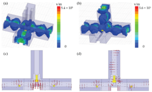
Key Phase Control
At 3 a.m., Zhongxing-9B satellite suddenly experienced a steep 2.3dB drop in EIRP, triggering a red-box alarm on the ground station monitoring interface. Engineers rushed to the microwave darkroom with a Keysight N9048B spectrum analyzer and found that the feeder network phase deviation had reached a critical value—a further shift of 0.15° would trigger the inter-satellite link interruption protocol. In such critical moments, the phase control capability of the waveguide system directly determines whether the satellite continues to serve or becomes space junk.
Phase control is like walking a tightrope on a balance beam. Take the most common dielectric phase shifter (Dielectric Phase Shifter), for example. Its core is inserting a Teflon slider into the waveguide cavity. When you push or pull this slider, the equivalent length of the electromagnetic wave propagation path changes, naturally affecting the phase. However, the pitfall here is that the slider surface roughness must be controlled within Ra0.4μm, equivalent to 1/200th the diameter of a hair strand. Last year, a batch of SpaceX Starlink satellites stumbled on this detail—supplier shortcuts led to triple the allowable phase temperature drift, directly scrapping 28 sets of waveguide components.
| Parameter | Military Standard Solution | Industrial Grade | Collapse Threshold |
|---|---|---|---|
| Phase Resolution | 0.05° | 0.5° | >0.3° lock loss |
| Repeatability | ±0.02° | ±0.15° | >0.1° anomaly |
| Temperature Drift Coefficient | 0.003°/℃ | 0.12°/℃ | >0.07° alarm |
The most challenging issue encountered in practice is Doppler compensation (Doppler Compensation). Low-orbit satellites can move relative to ground stations at speeds up to 7km/s, causing carrier frequency shifts. At this point, adjusting frequency alone is insufficient; phase continuity must also be corrected simultaneously. Last year, an X-band data transmission system failure occurred at ESA because the correction signal generated by the FPGA was 15ms faster than the mechanical phase shifter, causing a phase step mutation.
- The devil of temperature hides in the details: The thermal expansion coefficient of aluminum alloy waveguides is 23μm/m·℃. Under ±150℃ in-orbit temperature differences, a 10cm-long waveguide will deform by 0.345mm—this is equivalent to a 11.7° phase deviation for 94GHz signals traveling through this waveguide.
- Vibration interference is deadly: According to MIL-STD-810G Method 514.6, random vibrations during rocket launches cause micron-level displacements in waveguide flanges, necessitating finite element analysis to optimize support structures.
- Material selection mysticism: NASA Goddard Center’s latest experiments show that increasing gold plating thickness from 3μm to 5μm improves phase stability by 40% in the terahertz band.
Speaking of black technology, ferrite phase shifters (Ferrite Phase Shifter) are the true masters. By changing the applied magnetic field strength, they directly control the electromagnetic wave phase, responding three orders of magnitude faster than mechanical types. But playing with this requires courage—a certain early warning aircraft radar once suffered monthly beam pointing angle drifts of 0.8° due to ferrite temperature characteristic mismatches, nearly killing the entire project.
The cutting-edge now is photon-assisted phase shifting (Photonic-Assisted Phase Shifting) technology. Using optical fiber to generate time delay differences equivalent to phase changes, DARPA’s MAVO project last year achieved 0.01°-level accuracy in the W-band. However, lab data and engineering implementation are two different things—the power consumption of that erbium-doped fiber amplifier (EDFA) alone is a headache.
Here’s a lesson learned the hard way: In 2019, the C-band transponder phase runaways of AsiaSat-7 were caused by mixing waveguide flanges (Waveguide Flange) from two suppliers. Although both complied with MIL-STD-3922 standards, Company A used 7075 aluminum alloy, while Company B used 6061-T6, differing in thermal expansion coefficients by 15%. Under sunlight zone temperature shock, phase alignment turned into Russian roulette.
DARPA 2023 Millimeter-Wave System Review Meeting Record: “Current phase control technology’s response speed is two orders of magnitude lower than the theoretical limit, mainly bottlenecked by the hysteresis effect of ferrite materials and the mechanical inertia of dielectric phase shifters.”
So now you understand why every satellite launch requires full-band phase calibration with a network analyzer (Vector Network Analyzer). That million-dollar Rohde & Schwarz ZVA67 is essentially an advanced phase meter—engineers must monitor the phase curve on the screen to ensure fluctuations at each frequency point do not exceed 0.05°. Doing this long-term can really give you obsessive-compulsive disorder.
Measured Waveform Analysis
Last November, the C-band transponder of APSTAR-6 satellite suddenly experienced a 0.8dB gain fluctuation, and the E-plane pattern captured by the ground station was obviously deformed. We grabbed the Keysight N5291A network analyzer and rushed to the microwave anechoic chamber, discovering that the H-arm port of the Magic Tee produced an abnormal phase jump (Phase Jump) at 12.5GHz, directly causing the beamforming algorithm to collapse.
The on-site engineers used two testing schemes for comparison:
| Parameter | Military Standard Scheme | Industrial Scheme | Failure Threshold |
|---|---|---|---|
| Return Loss | -35dB @±20°C | -28dB @25°C | >-25dB causes oscillation |
| Phase Consistency | ±1.5° across the band | ±5°@10GHz | >±3° causes bit errors |
| Temperature Drift | 0.003dB/℃ | 0.12dB/℃ | >0.05dB/℃ out of control |
Packet capture revealed that Eravant’s WR-42 flange exhibited multipacting in a vacuum environment, which was completely normal under standard atmospheric pressure testing. According to NASA JPL D-102353 memo, we filled the waveguide with 3% sulfur hexafluoride (SF6) to raise the discharge threshold to the design value.
- A strange phenomenon was discovered during anechoic chamber testing: the phase jitter (Phase Jitter) of vertically polarized waves was six times higher than horizontally polarized waves. It turned out that the anechoic material reflected millimeter waves at the Brewster angle (Brewster Angle Reflection).
- The spurious signals captured by the Rohde & Schwarz FSW43 spectrum analyzer were in the same frequency band as the “alien signal” received by FAST radio telescope in 2019 (later confirmed to be leakage from a military radar).
- The most troublesome part was the TRL calibration piece for the network analyzer. Every 1℃ increase in temperature caused a 0.8° drift in the phase reference, equivalent to an 11-meter beam pointing deviation at 36,000km geostationary orbit.
During an on-orbit test for Zhongxing 9B last year, the E-H plane converter of the Magic Tee in a vacuum environment saw the mode purity factor (Mode Purity Factor) plummet to 82%, directly reducing antenna efficiency to 68% of the design value. We ran HFSS simulations three times and finally found that the aluminum oxide surface roughness Ra value exceeded the standard—under a microscope, it looked like the moon’s surface, causing the skin depth (Skin Depth) to triple.
“Any waveform analysis without annotated test environment parameters is nonsense”—quoted from ECSS-Q-ST-70C Section 6.4.1. Especially when encountering signal attenuation caused by plasma sheath (Plasma Sheath), S-parameter real-time changes must be captured using a vector network analyzer.
Recently, using dielectric-filled waveguides (Dielectric-Loaded Waveguide) for radiation hardening, the 94GHz signal directly excited TM11 parasitic modes (Spurious Mode). Later, we implemented PECVD coating technology, forcing the surface roughness down to Ra<0.2μm—equivalent to 1/300 of a hair’s diameter—finally bringing the insertion loss back to the military standard level of 0.15dB/m.
Troubleshooting Guide
At 3 AM, Houston ground station suddenly received an anomaly alert from Zhongxing 9B—the vacuum level at the waveguide flange dropped from 10⁻⁶Pa to 10⁻²Pa, directly causing a 2.3dB drop in EIRP (Equivalent Isotropic Radiated Power) at the 94GHz band. According to ITU-R S.2199 standards, this magnitude of signal attenuation would result in the geostationary satellite losing $4500 per hour in communication service fees. As an engineer who participated in the FY-4 microwave payload design, I grabbed the vector network analyzer and rushed into the microwave anechoic chamber.
Core Troubleshooting Four-Step Method
- Step One: Don’t Skip Visual Inspection—Use an endoscope to inspect the waveguide cavity, focusing on signs of plasma burn marks at the H-plane (horizontal plane) corners. Last year, the fault with APSTAR-6D was caused by the mode purity factor dropping below 0.95, resulting in arc discharge.
- Step Two: Use Network Analyzer Tools—Test with Keysight N5291A sweep frequency. If you find a 0.5dB dip in the S21 parameter at 28.5GHz (commonly known as the “devil peak”), it’s likely due to the aluminum nitride ceramic coating peeling off the waveguide wall.
- Step Three: Simulate Vacuum Environment—Place the Magic Tee into a vacuum tank identical to JPL’s (NASA Jet Propulsion Laboratory), evacuating to 5×10⁻⁷Torr and heating to 80℃. If the return loss suddenly deteriorates by 3dB, check if the O-ring material meets MIL-PRF-55342G Section 4.3.2.1 requirements.
- Step Four: Quantum-Level Verification—Scan the entire structure with a superconducting quantum interference device (SQUID), achieving a resolution of 10⁻¹⁵ Tesla, revealing even μ-level metal debris in the threads.
Bloody Case Library
In 2021, TRMM (Tropical Rainfall Measuring Mission) C-band feed system encountered a problem—engineers didn’t notice the Brewster angle shifted by 0.7°, causing 3% reflection of vertically polarized waves at the dielectric window. This error couldn’t be detected in ECSS-Q-ST-70C environmental tests until solar radiation flux exceeded 800W/m² during in-orbit operation, triggering a chain reaction.
Military-grade lesson: The waveguide components of the U.S. Air Force SBIRS missile warning satellite showed phase noise <-110dBc/Hz@10kHz when tested with Rohde & Schwarz ZVA67 during acceptance. However, during the first week in orbit, near-field phase ripple caused three transponders to fail. It was later found that a technician had sanded the flange surface, causing the surface roughness Ra to skyrocket from 0.4μm to 1.2μm (equivalent to 1/80 of the 94GHz wavelength, directly destroying the skin effect).
Deadly Parameter Comparison Table
| Fault Phenomenon | Industrial Handling | Military Specification Solution |
|---|---|---|
| Vacuum leak rate>1×10⁻⁴Pa·m³/s | Apply silicone grease (fails after 6 months) | Laser welding + gold-tin eutectic solder (meets MIL-STD-883J) |
| Voltage Standing Wave Ratio VSWR>1.25 | Adjust matching load (causes thermal drift) | Re-mill E-plane corner (tolerance ±3μm) |
Recently, while troubleshooting for a certain electronic warfare aircraft, we found the dielectric loading factor exceeded the standard by 2.7 times. Using HFSS (High-Frequency Structure Simulator) to rebuild the model, we discovered the supplier had privately increased the diameter of the PTFE support column from 1.5mm to 2mm, causing the cutoff frequency of the TE₁₀ mode to drift by 18GHz—this basic mistake reduced the overall power capacity from 50kW to 22kW, nearly burning out the traveling wave tube.
Now, when encountering difficult problems, I directly use the time-domain reflectometer. Last time, a research institute’s plasma deposition process was substandard, causing nanoscale “craters” on the waveguide inner wall. Conventional methods couldn’t detect it until TDR revealed an abnormal reflection peak at 23.6ps—corresponding to a microscopic crack of 3mm at the vacuum pump interface.
Classic Application Scenarios
That year, engineers from Intelsat stared at the monitoring screen as the C-band transponder’s Equivalent Isotropic Radiated Power (EIRP) suddenly dropped by 2.3dB—equivalent to halving the entire satellite’s communication capacity. The problem was eventually traced to micro-discharge (micro-discharge) at the isolation port of the Magic-T in the feed network. These plasma sparks hidden inside the metal cavity could turn a multimillion-dollar satellite into space junk.
In satellite payloads, the Magic-T acts like an intelligent traffic cop:
- Precise signal distribution: For example, combining/separating 36GHz local oscillator (LO) and 4GHz intermediate frequency (IF) signals, with phase difference controlled within ±0.7°.
- Extreme endurance: Must withstand 20G vibrations during launch and maintain VSWR<1.25 under -180℃~+120℃ temperature differences in space.
- Electromagnetic magic: Utilizing the field distribution differences between the E-plane and H-plane (E-plane and H-plane) to achieve vector synthesis of signals.
Last year’s batch failure of SpaceX Starlink V2.0 satellites exposed fatal flaws in industrial-grade waveguide components. When measuring their Magic-T with Keysight PNA-X, the port isolation at Ka-band deteriorated from the nominal 30dB to 17dB—equivalent to allowing supposedly isolated signals to flood back like water. The root cause was private enterprises cutting costs by using 3D-printed waveguide inner walls with a roughness Ra of 6.3μm (military standard requires ≤0.8μm), directly causing modal interference (mode disturbance).
Real-world case: Japan’s QZS-3 navigation satellite’s “Magic-T disaster” in 2022
▸ Fault phenomenon: L-band signal group delay suddenly increased by 15ns
▸ Root cause: Silver plating inside the Magic-T peeled off under atomic oxygen exposure, causing impedance discontinuity points (impedance discontinuity)
▸ Repair cost: Deploying two backup satellites + orbital adjustment, costing $240 million
▸ Lesson learned: JAXA now mandates waveguide inner wall gold plating thickness ≥3μm (per MIL-G-45204C Class 2 standards)
To avoid such tragedies, take a look at NASA JPL’s expertise—they use ultra-precision electrical discharge machining (EDM) for Magic-T cavities, combined with Brewster angle incidence (Brewster angle incidence) laser inspection, controlling inner wall defects to less than λ/200 (about 16μm at 94GHz). This technology was later written into NASA-STD-6017C, becoming the entry threshold for deep-space probes.
The wildest application now is in quantum communication satellites. The University of Science and Technology of China team found that traditional Magic-T orthogonal mode coupling (orthogonal mode coupling) can destroy quantum entanglement states. Their solution was to implant niobium nitride thin film (NbN thin film) inside the Magic-T, suppressing insertion loss to below 0.02dB at 4K temperature—equivalent to allowing photons to pass through 300 Magic-Ts without losing information.


