Table of Contents
Functionalit
Directional couplers and taps are common electronic elements employed in signal distribution, but they serve unique functions in this regard. Their purpose largely determines their applications and specific characteristics. The primary function of a directional coupler is that it selectively samples a small portion of the signal, generally 3-10%, without appreciably reducing its power or affecting the remainder of the signal’s transmission. They are most commonly employed in applications where the highest level of precision is necessary, such as laboratory measurements or high-frequency broadband systems, such as those often used in radio frequency testing and network analysis for calculation purposes.
In contrast, taps are used in situations involving the distribution of that signal to many users. In such a device, anywhere from 10% to 30% of the incoming signal power is “used,” as the tap may have several outputs or be duplicated to create a continuous diversion of signal to many locations. Taps are typically used in cable television or Internet service provider applications for residential or commercial buildings. As such, a fundamental distinction between the two devices is the amount of signal that is actually siphoned off by each. In practice, these distinctions translate into distinctive applications and apply to environments or contexts where each type of arrangement is most likely to be encountered.
For instance, in a large house or office building, a tap is more likely to be used because the same main signal must be distributed to many smaller locations. It must also be adequate to serve all of these end users even when the signal gets further away. Therefore, the relative amount of power associated with each device is relevant to its application. A tap accomplishes more because ends users can use it to tap into the network and make full use of it. A directional coupler, however, siphons off only as much power as is necessary to gauge the quality of the signal. A tap would be far less useful in a professional broadcast setting, where the quality of the signal to be aired is paramount.
In this instance, engineers may utilize a directional coupler to monitor the quality of a given signal without contaminating the one being broadcast to the audience. The use of directional couplers is thus more likely in settings where the quality of the data, signal strength, and its pure form are paramount. Similarly, although the purpose largely determines the nature of the devices, certain distinctions can always be made between them, such as the general amount of a signal each device “consumes.”
Directional Sensitivity
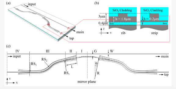
The feature that distinguishes between directional couplers and taps is the property of directional sensitivity. Directional couplers themselves are capable of discerning between which direction a signal is being run down a transmission line. This property as it turns out is critical in situations where signal diagnostics, or maintenance, is being carried out. An example of a typical specification of a directional coupler might include an isolation factor of 20dB between the forward and reverse direction. This way, measurements of the reflections of the signal due to mismatches of the impedance can be safely and accurately managed using the coupler.
On the other hand, taps are indifferent to the direction of signal flow, being a much simpler piece of equipment. Taps are used for sifferentiating signal power from a main line and supplying it to several smaller lines. The tap is entirely indifferent to the direction from which the power has come or to which the power is running. For this reason, taps are excellent for simple redistribution of impulses, such as that which occurs in cable at the community block, which is then divided by taps along the community block to each individual house. Directional sensitivity for a system that depends on the performance of the technology can be paramount.
For instance, in a telecommunications system using a directional coupler can help to determine very rapidly when a signal has been degraded, or begins to be too reflected, the implications of which speak towards the efficacy and ability of the network to run at a high performance level. In contrast, a tap in a network as the one described above would at best require twice the number of taps to measure the input and output of the given line and would still be impossible to use in troubleshooting large systemic problems. Once again, in the instance of a residential community block either a very fragile and intricate system such as a directional coupler could be employed at a tremendous cost, or a much simpler system could be used at a fraction of the cost for ensuring that each home received their signal as desired.
Signal Disturbance
Signal disturbance is the key factor to consider when making a choice between directional couplers and taps because of the impact it has on the transmission’s integrity and quality. Directional couplers are designed to minimize the disturbance to the main signal, as they are functionally reduced to sampling or monitoring the signal’s power. In practice, such a device may add only about 0.1 dB of insertion loss, which implies that nearly all of the original signal’s power will flow along the main transmission line, rather than be diminished significantly at all.
Instead, taps are designed to effectively divert most of the signal’s power into the second line, which must necessarily result in a severe loss of signal across the main line as well. In practice, a typical tap may incur an insertion loss of anywhere from 0.5 dB up to as much as 4 dB depending on the amount of tap outputs and the actual design of the tap. Such a level of the signal being lost may impact the quality and strength of the transmission, particularly if the tap is servicing multiple outputs or is just one part of a larger, widespread distribution scheme. In a broad-band internet distribution system that caters to a large residential complex, for example, taps would have to be used to ensure every apartment in the complex is serviced.
In such a system, every tap would experience a principal loss of signal that must then be managed depending on the needs of the users at wherever endpoint, including the requirement to use one or two taps for ensuring the last apartment in the complex’s signal is strong enough for high-speed internet use. A directional coupler could be used very differently in the same scenario – at that point in the line where the signal is first generated, for example; there it would be used to simply monitor the signal power without affecting its quality in the whole line.
Thus, the choice between the use of a directional coupler and a tap largely depends upon the need to balance the disturbance to the signal with the necessity to transmit the power to multiple users. Taps are more disruptive and require complex arrangements of monitoring and management of power distribution. At the same time, they are the only viable solution for applications where power needs to be proportionately distributed to as many users as possible. Directional couplers, in turn, have little to no impact on signal quality and are thus excellent for applications where the signal being higher quality is of the utmost importance, such as in the precise data communications or in testing or measurement setups.
Applications
The range of applications for directional couplers and taps is determined by their design and operation specifics and is substantially different. Directional couplers are used in high-precision and minimal-intrusive monitoring of signal paths. They offer functionality to differentiate between forward and reflected signals which is particularly useful in fields like telecommunications. For example, in the context of high-speed data transmission, directional couplers can be implemented to monitor power levels without affecting the data flow.
Thus, if an impedance mismatch takes place and the performance drops, it can be immediately diagnosed, interrupted, and the issue solved. Taps, in turn, are used in applications requiring power to be distributed to several receivers. A typical example is a situation in a cable television system where a signal from the service provider has to be fed to each separate household. In this instance, taps act to split the signal without the delivery of equal power levels to all users. They typically reduce it by 10% to 30% depending on the number of outputs. Thus, with this tap type, each user’s signal is of sufficient power despite the fact that the initial signal from the provider is evenly distributed at a lower level.
One of the typical applications for taps in professional audio that has to be supplied to all speakers on a music concert. In case of a directional coupler in the same application, they would individually monitor signal levels without interfering with the main path, ensuring that the overall audio quality at each speaker remains high. Thus, the choice between a directional coupler and a tap is vital for the system’s performance and operation efficiency.
Taps can be used in cases when signal integrity and precision monitoring are not critical and require the capability to lower the output signal without dropping the sound quality to maintain flawed wide distribution schemes. However, for applications where each decibel of signal loss may lead to performance problems taps are not applicable, and directional couplers should be implemented to ensure proper management and diagnostics.
Power Handling
One of the factors that must be considered when choosing between using taps or directional couplers is the power handling, as each is designed to accommodate a very different form of signal power. Directional couplers are intended to handle much lower power than taps by design. This is because directional couplers are used for signal sampling rather than distribution of power. As a result, a directional coupler might handle as little power as a few milliwatts to a few watts, depending on the design and purpose. This is useful for a wide range of applications, such as sensitive communication systems or RF testing setups, that require precise monitoring with minimal interference to the main signal path.
A tap, in contrast, is designed to handle much higher power loads due to the need to distribute signal power across multiple outputs. As an example, a tap splitting signal power to feed between five and twenty or more homes in a typical residential cable system would have to handle such power levels without degradation. How much power a tap is capable of handling depends on the number and size of its outputs. The power handling capacity of these taps can be substantial, on the order of several tens to hundreds of watts. As an example, a tap in a community broadband set up would have to distribute internet and cable television signals across many dozens of subscribers.
In order for this set up to work correctly, the tap must split the signal efficiently. Moreover, it must have the capability to handle such high power levels so as not to lead to attenuation of signal, leading to poor service for many customers. Lastly, let us take the example of a new RF communication device that is being tested. In this case, a directional coupler would be used to sample the signal being transmitted by the device.
By doing this, engineers could determine the power output and Transmitting frequency of the device without risk of damaging sensitive testing equipment. Since it is only necessary to divert a small portion of the signal being emitted by the device in order to accomplish the above, the power-handling capacity of a directional coupler is sufficient for this purpose.

