Table of Contents
Definition
In a waveguide 10 cm wide and 5 cm tall, the cut-off frequency for the TE10 mode is approximately 1.5 GHz, obtained by using the standard formulae for waveguides. If the frequency of operation falls below this value-for example, to 1.2 GHz-the wave becomes evanescent. This results in a decay constant (κ) of about 25 dB per centimeter, that is, the amplitude of the electromagnetic field decreases to 1% of its value within 8 mm.
This evanescent field is exploited in fibre couplers used to split or combine light signals and is usually about 10 µm for standard single-mode fibres. A DWDM system dealing with 40 channels at 100 GHz spacing can achieve data rates of more than 400 Gbps-something impossible without carefully managed evanescent interactions.
The most common application, TIRF microscopy, uses an evanescent field of 100-200 nm. One study analyzed protein-protein interactions by utilizing TIRF that has reached a detection limit of 10^-9 M concentration-proving just how sensitive this technology is.
Near-field Scanning Optical Microscopy (NSOM) uses evanescent fields to bypass the diffraction limit, achieving resolutions down to 20 nm. with companies like Intel using it to inspect transistor layers during chip manufacturing. An NSOM system, costing upwards of $500,000, offers unparalleled insights into nanostructures.

No Energy Propagation
In a standard rectangular waveguide operating below the cut-off frequency for the TE10 mode, energy attenuation can reach 20 dB per millimeter, meaning the field strength diminishes to less than 1% within a span of just 5 mm.
Near-field scanning optical microscopy (NSOM) takes advantage of the non-propagating nature of evanescent waves to achieve spatial resolutions beyond the diffraction limit of light, often down to 20 nm or less.
Atypical evanescent wave biosensor can detect refractive index changes as small as 10^-5, enabling the identification of trace biomolecules at concentrations as low as 10^-12 M.
In a waveguide designed for a frequency range of 2–5 GHz, an abrupt change in geometry can induce evanescent modes that cause up to 30% reflection loss if not properly managed.
Mathematical Characterization
The propagation constant for a waveguide is given by the relation between the wavenumber kkk and the cutoff wavenumber kck_ckc as:
β=k2−kc2.\beta = \sqrt{k^2 – k_c^2}.β=k2−kc2.
For frequencies below the cutoff frequency, f<fcf < f_cf<fc, the expression k2−kc2k^2 – k_c^2k2−kc2 becomes negative, and β=iκ\beta = i\kappaβ=iκ, where κ=kc2−k2\kappa = \sqrt{k_c^2 – k^2}κ=kc2−k2 defines the rate of exponential decay. For a rectangular waveguide with a cutoff frequency of 3 GHz, operation at 2 GHz would correspond to a decay constant κ≈10 Np/m10 \\, \mathrm{Np/m}10Np/m, implying that the strength of the field decreases by a factor of eee (approximately 37%) every 0.1 meters.
The fact that β\\betaβ is purely imaginary has immediate implications for the form of the field components. In the case of an evanescent mode, the electric field (EEE) and magnetic field (HHH) solutions are of the form:
E(x,z)∝eiωte−κz,E(x, z) \propto e^{i\omega t}e^{-\kappa z},E(x,z)∝eiωte−κz,
where zzz denotes the direction of decay. It is readily seen from this solution that although the field oscillates in time, it decays in space, so that only a highly localized field close to the source is possible. As an example, assuming a decay rate of κ=20 Np/m:/mκ=20Np/m, one obtains a field strength at z=10 cm:/m that is about 0.14% of its value at the source.
Evanescent modes also appear in the case of boundary phenomena such as total internal reflection. Taking a typical case of light propagation from one medium with n1=1.5 to another with n2=1.0 at an angle larger than the critical angle-for instance 41.8°, the transmitted wave will be an evanescent one. Its penetration depth into the second medium is given by
d=λ2πn12sin2θ−n22.d = \frac{\lambda}{2\pi\sqrt{n_1^2 \sin^2\theta – n_2^2}}.d=2πn12sin2θ−n22λ.
For light at a wavelength of 650 nm650 , mathrm{nm}650nm, the skin depth may be 100 nm100 , mathrm{nm}100nm, in which case near-surface interactions are possible with minimal energy transfer.
Cut-off Condition
Evanescent modes occur under the cut-off condition, in a rectangular waveguide with a width (a) of 2 cm2 , mathrm{cm}2cm, the cut-off frequency for the dominant mode TE10 can be calculated using the formula:
fc=c2a,f_c = \frac{c}{2a},fc=2ac,
where ccc is the speed of light (3×10⁸ m/s3 \times 10^8 , \mathrm{m/s}3×108m/s). Substituting the dimensions, the cut-off frequency is 7.5 GHz7.5 , \mathrm{GHz}7.5GHz. If the operating frequency is 6.5 GHz6.5 , \mathrm{GHz}6.5GHz.
In the same waveguide, the TE20 mode has a cut-off frequency of 15 GHz15 , \mathrm{GHz}15GHz, and the TM11 mode has a cut-off at approximately 12 GHz12 , \mathrm{GHz}12GHz. These higher-order modes remain evanescent until the operating frequency exceeds their respective thresholds.
A waveguide filter with a TE10 cut-off frequency of 8 GHz8 , \mathrm{GHz}8GHz is used to reject signals below 7.8 GHz7.8 , \mathrm{GHz}7.8GHz, ensuring clean transmission in the 8–12 GHz8–12 , \mathrm{GHz}8–12GHz range.
As the operating frequency approaches fcf_cfc, the propagation constant β\betaβ approaches zero, causing the group velocity to decrease. Near f=0.99fcf = 0.99f_cf=0.99fc, the group velocity might drop to just 1%1%1% of the speed of light, while the phase velocity increases significantly, sometimes exceeding 10c10c10c.
A typical single-mode fiber has a cut-off wavelength of 1260 nm1260 , \mathrm{nm}1260nm. This principle ensures minimal modal dispersion in communication networks, achieving data rates exceeding 400 Gbps400 , \mathrm{Gbps}400Gbps for long-distance transmission.
Spatial Decay
This behavior is mathematically described by the equation:
E(z)=E0e−κz,E(z) = E_0 e^{-\kappa z},E(z)=E0e−κz,
For propagation below cut-off frequency in a rectangular waveguide the decay constant may be as large as 30 Np/m30 , \mathrm{Np/m}30Np/m so that the strength of the field drops by 95% over a distance of only 10 cm10 , \mathrm{cm}10cm.
The evanescent field in the cladding of an optical fiber decays exponentially. Its penetration depth may vary between approximately 50 nm50 , \mathrm{nm}50nm and 200 nm200 , \mathrm{nm}200nm depending on refractive index contrast. Assuming the refractive index of the core is 1.48 and that of cladding is 1.46, the evanescent wave would penetrate about 100 nm100 , \mathrm{nm}100nm, enabling interaction with external media. This is highly important in sensors based on evanescent waves, where the field interacts with the analytes near the surface of the fiber to detect changes in refractive index, normally with sensitivities higher than 10−510^{-5}10−5.
In near-field communication, it is the range of the evanescent field that marks the effective. A typical NFC system works at 13.56 MHz13.56 , \mathrm{MHz}13.56MHz, based on an evanescent field that decays rapidly beyond 4 cm4 , \mathrm{cm}4cm to assure secured short-distance communication. The field strength may fall from 10 V/m10 , \mathrm{V/m}10V/m at 1 cm1 , \mathrm{cm}1cm to 0.01 V/m0.01 , \mathrm{V/m}0.01V/m at 10 cm10 , \mathrm{cm}10cm, thus limiting the range.
In TIRF microscopy, the evanescent field reaches only a couple of hundred nanometres into the sample. The typical TIRF setup might achieve a penetration depth of 150 nm, allowing single molecule detection at concentration down to 10−12 M.
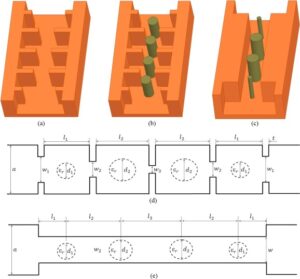
Evanescent modes in waveguide discontinuities result in the coupling of power out of the waveguide. A 90∘90^\circ90∘ bend in a rectangular waveguide can experience up to a 20% power loss owing to the evanescent coupling at the sharp corner. This is reduced by having smoother transitions or by incorporating matching structures; the resultant losses are then less than 5%.


