Table of Contents
Identify Waveguide Dimensions and Mode
The cutoff frequency of a waveguide can only be calculated if the waveguide’s dimensions are accurately measured. Among the critical dimensions of a standard rectangular waveguide for an X-band satellite communication system are the width 𝑎a mm and the height 𝑏b mm. A typical size for an X-band standard might be 23 mm x 10 mm. In addition to the correct measurement of dimensions, one must consider the mode for which the waveguide will be operational. TE and TM modes of a waveguide have different effects on the propagation modes in the waveguide and the mode in use determines the cutoff frenetic, among other properties of the waveguide.
The TE10 mode is a standard in the use of radar systems. It is the reason why dominant plane of the mode is solved while the general form of Maxwell’s equations is used to model the other field. It provides a simple understanding as the mode can be understood to support one of the predominant electric field component. As such, the use of the mode facilitates higher efficiency of the transmission.
Annamalai and Ohta gave a simple example of a link in the mobile operators’ telecom network. A good cut-off frequency and minimal loss can inform the suitable mode of the waveguide and the size the waveguide should meet. For instance, a size of 72 mm x 34 mm can be appropriate for use with the microwave mobile system. This medium size for lower microwave frequencies would give cut of frequency of around GHz for TE01 mode, please see figure 9.1 of. This size would be sufficient for a wide range of microwave application. Alternatively, the size can be changed to 80 mm in width to cover lower frequencies compared to the previous dimension. This would lead to the decreased cut off frequency. The new dimension would be both economical in terms of material used and suitable for application needing broader bandwidth.

Determine the Mode Numbers
Optimization of the function of a waveguide depends on the appropriate choice of mode numbers. 𝑚m and 𝑛n define the number of field variations along the different dimensions of the waveguide. For example, in a rectangular waveguide, 𝑚m will define the number of half-wavelength variations along the width and 𝑛n along the height of the waveguide. In situations revolving around the transmission of electromagnetic waves, the waveguide would essentially be considered a transmission line for signals along with the receiver for waves.
Physical Setting
In the case of signals transmitted through a satellite, the most appropriate mode number would be the TE10, which means 𝑚=1m=1 and 𝑛=0n=0. TE10 provides the single mode of wave with minimum losses at high-frequency ranges. In this case, it is important to transmit signals with high efficiency and least distortion for the maintenance of the clearness of communication links.
Experience of Final Radar System Design
In the final design setting, the choice between the two modes is ultimately transformative for the overall performance of the system, its frequency variability, and efficiency. The TE10 mode would be beneficial due to the fact of its lower cut-off frequency. The radar would then be able to operate in a wider frequency range, opening up the possibility for a much bigger range of different speeds and objects aimed to be detected to be easily tuned to the appropriate frequency. For instance, changing the value of 𝑚m from 1 to 2 might increase the cut-off frequency by double the size of the previous cut-off point. So, with cut-off frequency 3 GHz with mode TE10, it increases to 6 GHz with TE20, which can be the difference between detecting close speed cars vs those much farther and faster cars with TE10. Telecommunications engineers create mathematical models of the behavior of the waveguide relative to signal sources by simulating the possible number of fields with different m and n values. Then by the results of the frequency dynamics, the waveguide can be chosen selectively along the specific range of frequencies along which it is intended to function. It also allows tailoring the requirements of the waveguide in dialogue with the manufacturers, as different materials have different costs and specifications.
Apply the Formula for Cutoff Frequenc
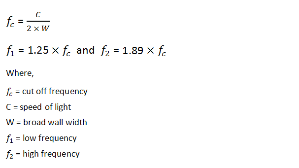
Using the formula for the cutoff frequency is a straightforward yet vital step in the design and analysis of waveguides. This formula helps determine the lowest frequency at which a given mode will effectively propagate through the waveguide without significant loss. The formula for a rectangular waveguide, for instance, is:
𝑓𝑐=𝑐2(𝑚𝑎)2+(𝑛𝑏)2fc=2c(am)2+(bn)2
where 𝑐c represents the speed of light in vacuum (approximately 3×1083×108 meters per second), 𝑚m and 𝑛n are the mode numbers, and 𝑎a and 𝑏b are the dimensions of the waveguide’s cross-section.
In a practical scenario, consider a telecommunications engineer designing a waveguide for a 5G cellular network. The engineer might choose a waveguide with a width 𝑎a of 22 mm and a height 𝑏b of 10 mm, targeting the TE10 mode for optimal performance. Plugging these values into the formula would yield a cutoff frequency that ensures the waveguide efficiently handles the designated frequency range of the network.
For example, using the dimensions and mode numbers stated, the cutoff frequency calculation would look like this:
𝑓𝑐=3×1082(10.022)2+(00.01)2≈6.82 GHzfc=23×108(0.0221)2+(0.010)2≈6.82GHz
This value is crucial for confirming that the waveguide operates efficiently within the required frequency range, avoiding transmission below this frequency where the waveguide cannot effectively transmit power, potentially leading to system inefficiencies.
Calculate the Cutoff Frequency
Once the mode numbers and dimensions are established, the next step is to calculate the cutoff frequency using the derived formula. This step is pivotal in ensuring that the waveguide will function correctly within the intended frequency range.
Take the example of a network engineer tasked with enhancing the WiFi infrastructure in a large corporate office. After determining that a TE10 mode is most suitable for the setup, the engineer measures the waveguide’s width 𝑎a as 15 mm and its height 𝑏b as 8 mm. Plugging these values into the cutoff frequency formula provides:
𝑓𝑐=3×1082(10.015)2+(00.008)2≈10 GHzfc=23×108(0.0151)2+(0.0080)2≈10GHz
This calculation confirms that the waveguide can efficiently handle frequencies up to 10 GHz, which is ideal for high-speed WiFi that operates around these frequencies.
To validate the performance and ensure no unexpected losses occur, it’s critical to compare this theoretical cutoff frequency with practical measurements. For instance, the engineer might use a network analyzer to measure the actual frequency response of the waveguide. If the measured cutoff frequency closely matches the calculated 10 GHz, the engineer can confirm the waveguide’s capability and reliability.
Such precise frequency management not only optimizes the network’s performance but also reduces costs by preventing over-specification of materials. Choosing the correct waveguide dimensions and mode directly impacts the material costs and efficiency of the system. By confirming that the waveguide performs optimally at the required frequency, the engineer maximizes both the quality of the WiFi network and the budget allocated for infrastructure upgrades.


