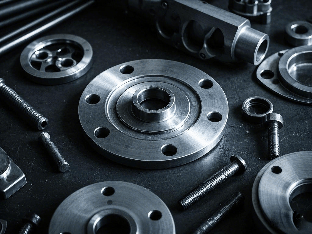
+86 29 8881 0979

April 2025

What Limits Waveguide High Pass Filters

Waveguide high pass filters are limited by factors like cutoff frequency, typically starting from 1GHz, and maximum power handling, often around 100W for smaller units. Physical dimensions and material losses also restrict performance, affecting bandwidth and insertion loss, crucial for effective signal processing in microwave communications. High-Pass Filter Limitations Last month, the European Space Agency’s […]

What Limits Waveguide High Pass Filters Read More »

What’s Inside a Waveguide Calibration Kit

A waveguide calibration kit includes components like shorts, opens, and loads for VSWR measurement, and sliding shorts for phase calibration. Typically, it contains items such as a 2.92mm connector kit, with precision parts ensuring accurate signal calibration across various frequencies, essential for testing and validating RF systems. Calibration Kit Disassembly That day in the ESA

What’s Inside a Waveguide Calibration Kit Read More »

Why Are Waveguide Low Pass Filters Crucial

Waveguide low pass filters are crucial in RF and microwave circuits, reducing interference by attenuating frequencies above 1 GHz. They ensure signal purity, enhance system efficiency, and protect sensitive components from high-frequency noise, making them indispensable in communication systems. How Important Low-Pass Filtering Is Last year, we just finished handling the VSWR fault (voltage standing

Why Are Waveguide Low Pass Filters Crucial Read More »

When to Use Waveguide Flange Adapters

Waveguide flange adapters are used when connecting waveguide components with different flange types or sizes, ensuring minimal signal loss. They’re essential in systems operating above 1 GHz, where precise alignment and tight sealing are critical to maintain performance and prevent leakage, supporting efficient signal transmission. Flange Transition Timing Last year, the ESA’s AlphaSat mission nearly

When to Use Waveguide Flange Adapters Read More »

Why Use Waveguide Dividers in Satellites

Waveguide dividers in satellites ensure precise signal distribution (0.1dB imbalance) across multiple transponders, handling high power (50W+) at Ka/Q bands (26-40GHz). Their low insertion loss (<0.3dB) and phase stability (±2°) optimize payload efficiency. Gold-plated aluminum construction withstands space radiation and thermal cycling (-40°C to +85°C). Function of Satellite Waveguide Dividers Last year, the sudden vacuum

Why Use Waveguide Dividers in Satellites Read More »

How Durable Are Waveguide Pressure Windows

Waveguide pressure windows typically withstand 50-100 psi differential pressure when constructed with 0.060″ thick alumina ceramic (Al₂O₃) for X-band (8-12 GHz) applications, exhibiting less than 0.05 dB insertion loss. For harsh environments, 0.090″ beryllia (BeO) windows handle 150+ psi with superior thermal conductivity (330 W/mK), maintaining VSWR <1.1:1 across 10% bandwidth. Lifetime Testing Last year’s

How Durable Are Waveguide Pressure Windows Read More »

How Thick Should Waveguide Shims Be

The thickness of waveguide shims depends on the required frequency adjustment and flange type, typically ranging from 0.001″ to 0.020″ (0.025-0.5mm) for standard WR-90 waveguides. For precise impedance matching at X-band (8-12GHz), use 0.004″ brass shims to compensate for λ/4 wavelength gaps, ensuring VSWR remains below 1.2:1. Always measure flange separation with micrometer calipers and

How Thick Should Waveguide Shims Be Read More »

How to Calculate Waveguide Twist Specifications

When calculating waveguide twist specifications, engineers must account for the operating frequency range (e.g., 18-26.5 GHz for K-band WR-42 waveguide) and required polarization rotation (typically 90° with ±0.25° precision). Critical parameters include maintaining insertion loss below 0.2 dB across the band, achieving VSWR under 1.2:1, and ensuring >35 dB polarization isolation, verified through vector network

How to Calculate Waveguide Twist Specifications Read More »

How to Select Waveguide Detector Diodes

When selecting waveguide detector diodes, focus on matching the diode’s frequency range to your waveguide band (e.g., 26.5-40 GHz for Ka-band WR-28 systems), ensuring sensitivity meets application requirements (typically -30 to -50 dBm detection threshold), and verifying power handling capacity (usually 10-100 mW continuous wave). Critical parameters include video resistance (1-5 kΩ for proper impedance

How to Select Waveguide Detector Diodes Read More »

Scroll to Top
Blank Form (#3)