+86 29 8881 0979

September 17, 2025

How do satellite antennas work

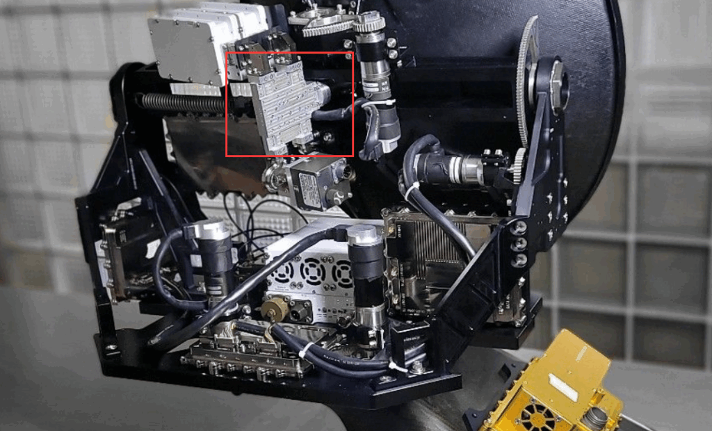
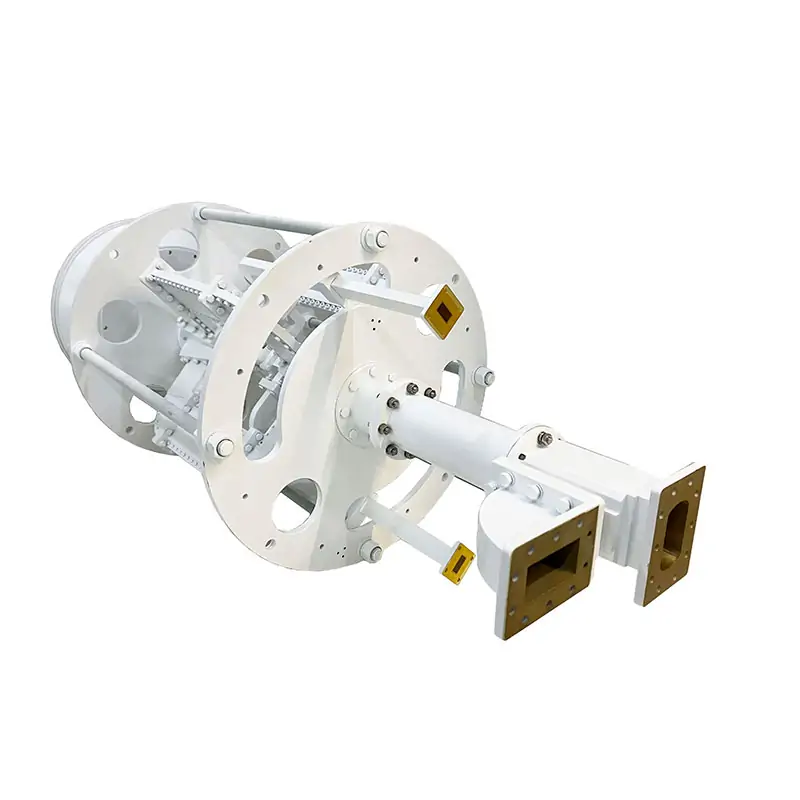
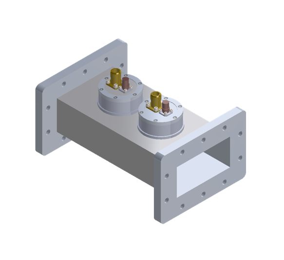
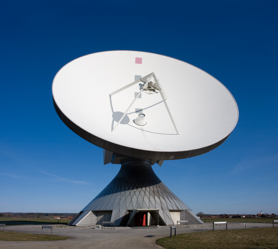
Satellite antennas operate via parabolic reflectors that focus electromagnetic waves onto a feed horn; a 3-meter diameter dish in Ku-band (12-18GHz) achieves ~40dBi gain, directing signals toward satellites. During transmission, electrical signals convert to waves at the feed, reflected into parallel beams by the parabola; reception reverses this, focusing incoming waves (error <0.1° in azimuth/elevation) […]

How do satellite antennas work Read More »

How do you test a directional coupler

To test a directional coupler, connect it to a signal generator (output: +10dBm, 2-4GHz) and spectrum analyzer. Measure input power (Pin) at the main port, coupled power (Pcouple) at the coupled port, and isolated port power (Piso). Calculate insertion loss (Pin-Pthru, typical 0.5-2dB), isolation (Pin-Piso ≥20dB), and directivity (Pcouple-Piso ≥30dB) to validate performance. Measure Insertion

How do you test a directional coupler Read More »

What are the factors contributing to the loss inside a wr187 waveguide

Losses in WR187 waveguides (8.2-12.4GHz, a=47.55mm, b=23.78mm) stem from conductor surface roughness (Ra>0.5μm adds 0.1-0.3dB/cm), dielectric oxidation (tanδ=1e-4 vs. 1e-6 clean, +0.02-0.05dB/cm), mode conversion at misaligned flanges (>λ/100, λ≈30mm at 10GHz, +0.1-0.3dB), and scattering from scratches (>λ/20, +0.05-0.15dB/cm). Wall Material Conductivity Impact The conductivity of the wall material is a primary factor in determining the

What are the factors contributing to the loss inside a wr187 waveguide Read More »

What is the beamwidth of quad-ridged horn antenna

A quad-ridged horn antenna typically has a beamwidth of 60-80° in X-band (8-12 GHz), varying with ridge spacing and length; lower bands (e.g., L-band) may reach 90-100°, while higher Ku-band narrows to 50-60°, ideal for satellite communication directional coverage. Basic Antenna Beamwidth Explanation​​ Antenna beamwidth, specifically the ​​Half-Power Beamwidth (HPBW)​​, is the most critical metric

What is the beamwidth of quad-ridged horn antenna Read More »

What are the 7 radio waves

The 7 radio waves span ELF (3-30Hz, submarine comms), SLF (30-300Hz, underground), ULF (300-3kHz, geophysics), VLF (3-30kHz, nav beacons), LF (30-300kHz, AM), MF (300-3MHz, AM), HF (3-30MHz, shortwave), each with distinct propagation for specialized uses. Radio Waves in Broadcasting Today, ​​over 44,000 licensed radio stations​​ operate globally, with the ​​AM band (530–1700 kHz)​​ and the

What are the 7 radio waves Read More »

What messes with radio waves

Rainfall attenuates radio waves, with Ku-band signals losing 10-15 dB during heavy storms; concrete buildings block signals, causing over 20 dB loss in cities. Nearby Wi-Fi (2.4 GHz) or Bluetooth devices introduce noise, reducing clarity by up to -30 dBm. Tall Buildings Block Signal Radio signals, especially those above 1 GHz like 5G (which often

What messes with radio waves Read More »

Introducing the High Power Differential Phase Shift WG Circulator

The High Power Differential Phase Shift WG Circulator operates in X-band (8-12 GHz), supporting 500W peak input power with <0.5 dB insertion loss and >40 dB isolation. Its optimized ferrite structure minimizes phase error to ±2°, ensuring stable signal routing in high-power radar systems. What It Is and How It Works A High Power Differential

Introducing the High Power Differential Phase Shift WG Circulator Read More »

Ka-Band 4-Port Diplexer with Circular Polarization for Antenna Networks

The Ka-band 4-port duplexer supports circular polarization and is suitable for antenna networks. The frequency range is usually 26.5 to 40 GHz. It can achieve efficient merging and separation of multi-path signals, ensuring a transmission rate of more than 10 Gbps. The polarization direction must be accurately calibrated during installation to optimize performance. Ka-band Characteristics

Ka-Band 4-Port Diplexer with Circular Polarization for Antenna Networks Read More »

What is the difference between coupler and waveguide combiners

Couplers are used to distribute or combine signals in proportion (such as 10dB coupling), while waveguide combiners directly integrate multiple signals and are suitable for high-power scenarios. Both operate in a specific frequency band, such as 2-40GHz, but have different structures and functions. Coupler Basics During ChinaSat 9B’s orbital tests, engineers found EIRP suddenly dropped

What is the difference between coupler and waveguide combiners Read More »

Scroll to Top
Blank Form (#3)