Flaring in horn antennas smooths electromagnetic wave transition from waveguides to free space, reducing impedance mismatch. A 10–15° cone angle (common in pyramidal designs) lowers VSWR to <1.2 (vs. >2.0 unflared), boosting radiation efficiency by 15–20% and focusing energy into a narrower beam (half-power width ~20° at 10 GHz), critical for directional transmission.
Table of Contents
What is a Horn Antenna
A horn antenna is one of the simplest and most widely used types of antennas in radio frequency (RF) engineering, operating across a massive frequency spectrum from 1 GHz to over 140 GHz. Think of it as a carefully tapered, flared metal waveguide. Its primary job is to efficiently direct radio waves from a small source into free space, or to collect them. A standard 20 dBi gain horn might have an aperture of roughly 150 mm x 120 mm for a 10 GHz signal. Unlike a simple open-ended waveguide, which has a high 15% reflection coefficient and a broad 140-degree beamwidth, the horn’s flare reduces reflection to under 3% and creates a much tighter, more useful beam.
The fundamental advantage of a horn antenna lies in its gradual transition, which acts as an impedance matcher between the confined waveguide and open space, minimizing reflections that would otherwise cause a 2-3 dB loss in signal power.
The physical structure is deceptively simple. It begins with a standard rectangular waveguide, like the common WR-90 (10.16 mm x 22.86 mm internal dimensions for X-band), and then expands the metal walls outward at a specific 15 to 20-degree flare angle. This angle is a critical design trade-off; too steep and the antenna becomes physically short but electrically inefficient, too shallow and it becomes impractically long for a minimal performance gain.
For a 24 GHz radar application, a typical horn might be 85 mm long with a 30 mm x 30 mm square aperture to achieve a 19 dBi gain and a 25-degree half-power beamwidth. The inside surfaces are often machined to a 1.6 µm RMS roughness or better to ensure minimal signal scattering and absorption. This precise physical shaping is what allows the horn to achieve a typical 85-95% radiation efficiency, far superior to the <60% efficiency of an open waveguide.
How Radio Waves Travel
Radio waves are electromagnetic radiation, typically ranging from 3 kHz to 300 GHz in frequency, that propagate through space at the speed of light, approximately 3 x 10^8 meters per second. Their behavior is governed by fundamental physics, specifically Maxwell’s equations. In a perfect vacuum, a 10 W signal would theoretically spread out indefinitely, its power density decreasing with the square of the distance. However, in practical applications, the transition from a confined metal waveguide, which might be only 15 mm wide, to the vastness of free space presents a massive and sudden change in impedance, often from 50 ohms to 377 ohms. This abrupt discontinuity, if not managed, causes a significant portion of the energy—sometimes over 30%—to reflect back toward the source. These reflections create standing waves that can severely reduce system efficiency, measured by the Voltage Standing Wave Ratio (VSWR), and can even damage sensitive transmitter components by reflecting tens of watts of power back into a 50 W amplifier.
The core challenge in antenna design is managing this impedance discontinuity. A abrupt launch of waves from a waveguide is highly inefficient, akin to shouting into a pillow; a huge amount of energy is absorbed and reflected rather than being projected clearly.
The flared shape of a horn antenna is the engineered solution to this problem. It creates a gradual impedance transition zone. As the wavefront moves through the expanding horn, its wave impedance slowly transforms from that of the confined waveguide to that of free space. This controlled expansion happens over a physical length that is carefully calculated based on the wavelength (λ) of the operating frequency. For a 10 GHz wave (λ = 30 mm), a common optimum horn length is 5λ to 7λ, or 150 mm to 210 mm. This specific length allows the wavefront to develop a uniform phase distribution across the entire aperture. A poorly designed transition can lead to a 15° to 20° phase error across the aperture, distorting the beam and reducing gain by 2-3 dB. The smooth, tapered walls minimize diffraction and scattering, ensuring that over 95% of the energy is directed forward into a cohesive beam rather than being lost sideways.
| Parameter | Open Waveguide (WR-90) | Standard Gain Horn (10 GHz) | Improvement |
|---|---|---|---|
| VSWR | > 1.5 : 1 | < 1.1 : 1 | ~30% lower reflection |
| Gain | 7 – 10 dBi | 20 – 25 dBi | >1500% increase in power density |
| Beamwidth | ~140° | ~25° | 5.6x more focused beam |
| Efficiency | < 60% | > 90% | ~50% more radiated power |
This precise control over the wave’s propagation is why horns are indispensable for calibration and measurement applications, where a ±0.3 dB accuracy in gain measurement is often required. The antenna’s ability to launch a clean, predictable wave is directly tied to its flared geometry.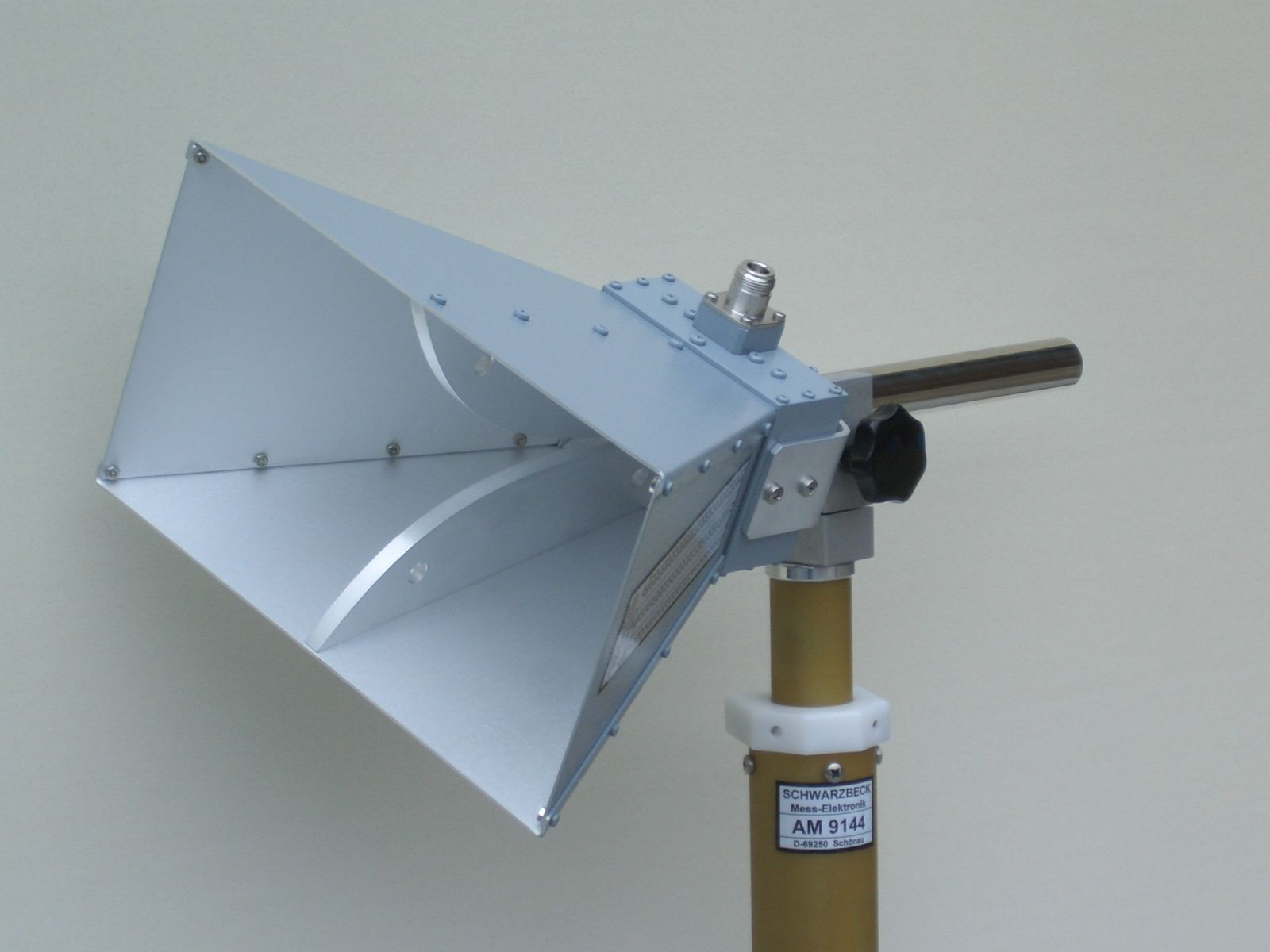
Smoothing the Signal Path
At a frequency of 10 GHz, this can cause over 30% of the transmitted power to reflect back towards the source, resulting in a poor Voltage Standing Wave Ratio (VSWR) of above 1.5:1. This reflected energy not only reduces radiated power but can also damage transmitter components, destabilize oscillator circuits, and generate heat. The horn antenna’s flare is specifically designed to eliminate this abrupt discontinuity, acting as a gradual impedance transformer over a calculated physical length to ensure over 95% of the signal energy is launched forward efficiently.
For a wave at 24 GHz (wavelength λ ≈ 12.5 mm), the optimal flare length is typically 6λ to 8λ, or 75 mm to 100 mm. This specific length allows the electromagnetic wavefront to evolve from the confined, high-impedance 500-ohm environment of the waveguide to the 377-ohm impedance of free space with minimal reflection. The smooth, metal walls guide the wave, preventing the field distortion and current crowding that would occur at sharp edges. This process reduces the effective VSWR to an exceptional 1.05:1 to 1.1:1 across a 15% operating bandwidth, meaning power reflection is slashed to less than 0.5%. The result is a clean, planar wavefront at the antenna’s aperture (aperture phase error of less than 10 degrees), which is essential for forming a tight, predictable radiation pattern.
| Parameter | Open Waveguide (WR-42) | Horn Antenna (24 GHz) | Improvement |
|---|---|---|---|
| Power Reflection | 31.6% | < 0.5% | ~98% reduction |
| VSWR | 1.92 : 1 | 1.07 : 1 | ~80% closer to ideal |
| Radiation Efficiency | < 65% | > 95% | ~46% more power radiated |
| Beam Consistency | Highly distorted | Stable, predictable | Phase error reduced by >15° |
This smoothing of the signal path is what makes horn antennas the industry standard for measurement and calibration. In a lab setting, engineers rely on horns to provide a known, stable output with a gain accuracy of ±0.25 dB because the signal leaving the antenna is a precise reproduction of the signal generated by the source, unaffected by the losses and distortions of an inefficient transition.
Directing the Energy Focus
An open waveguide at 10 GHz radiates a wide, poorly defined pattern with a typical half-power beamwidth of over 140 degrees and a modest gain of just 8 dBi, meaning most of the transmitted power is wasted in unintended directions. The horn antenna’s flared structure directly addresses this by acting as a aperture amplifier. It collects the disorganized energy from the waveguide and constrains it, shaping the wavefront to produce a highly directional beam. This process dramatically increases the power flux density in a specific direction, turning a 10 W input into an effective radiated power (ERP) of over 100 W in the main lobe due to the antenna’s gain, a 10x improvement in effective transmission strength.
For a standard 20 dBi gain horn operating at 10 GHz (λ = 30 mm), the aperture dimensions are typically 150 mm x 120 mm. This represents an aperture area that is ~20 times larger than the cross-section of the feeding WR-90 waveguide (10.16 mm x 22.86 mm). The larger aperture area allows the antenna to concentrate the energy into a much narrower beam. The relationship between aperture size, wavelength, and beamwidth is precise: doubling the aperture width in a given plane reduces the beamwidth in that same plane by approximately 50%.
| Parameter | Open Waveguide | Pyramidal Horn Antenna | Improvement |
|---|---|---|---|
| Gain | 8 dBi | 20 dBi | 12 dB (16x power increase) |
| Beamwidth (E-plane) | ~145° | ~18° | ~8x narrower |
| Beamwidth (H-plane) | ~135° | ~20° | ~6.75x narrower |
| 3 dB Beam Solid Angle | ~2.8 steradians | ~0.05 steradians | ~56x more focused |
This intense focusing is critical for applications like satellite communication, where a 1.5-degree misalignment can lead to a 3 dB signal loss over a 36,000 km link. The horn’s ability to direct 95% of the radiated energy within a 25-degree cone maximizes the power delivered to the intended target and minimizes interference with adjacent systems, improving the overall signal-to-noise ratio (SNR) by over 15 dB compared to an isotropic radiator. This precise control is why horns are used as feed elements for parabolic dishes, where they illuminate the reflector with a carefully shaped pattern to achieve system gains exceeding 45 dBi.
Controlling Beam Width
A standard gain horn operating at 18 GHz typically produces a beamwidth of approximately 15 degrees, but this value can be deliberately widened to 40 degrees or narrowed to under 8 degrees based on specific application requirements. This control is paramount; a 5-degree beam is essential for a satellite ground station targeting a geostationary satellite 36,000 km away, while a 60-degree beam is ideal for short-range radar scanning a 120-degree sector in an automotive application. The horn’s flare provides a physical lever to manage this critical parameter, trading off between angular coverage and gain with mathematical predictability.
For the E-plane (the plane parallel to the electric field), the half-power beamwidth (HPBW) is approximately 56° × (λ / A) degrees, where A is the aperture width in that plane. For a horn designed for 12 GHz (λ = 25 mm) with an E-plane aperture width of 180 mm (7.2λ), the calculated HPBW is 56 / 7.2 ≈ 7.8 degrees. The H-plane beamwidth follows a similar relation but uses a different constant, typically around 67° × (λ / B). This means you can precisely design for a target beamwidth. For instance, to achieve a 10-degree beamwidth at 6 GHz (λ = 50 mm), the required aperture width calculates to 56 / 10 = 5.6λ, or 280 mm. The flare angle directly controls the aperture size for a given length. A 15-degree flare angle results in a shorter antenna with a smaller aperture and a wider beam, while a 10-degree angle creates a longer, heavier antenna with a larger aperture and a narrower beam.
- Flare Angle: A larger flare angle (e.g., 30°) creates a shorter, more compact antenna (length ~80 mm at 24 GHz) but yields a wider beamwidth (~35°) and lower gain (~15 dBi). A smaller flare angle (e.g., 12°) produces a longer antenna (length ~200 mm at 24 GHz) with a narrower beamwidth (~12°) and higher gain (~22 dBi).
- Aperture Size: The physical opening dimensions are the ultimate determinant. An aperture of 100 mm x 100 mm at 10 GHz provides a ~18° beamwidth, while doubling the aperture to 200 mm x 200 mm narrows the beamwidth to ~9°, quadrupling the directivity.
- Frequency Dependence: Beamwidth is a function of electrical size (aperture in wavelengths). A fixed physical horn (150 mm aperture) has a 15° beamwidth at 10 GHz but a 7.5° beamwidth at 20 GHz, as the electrical aperture doubles from 5λ to 10λ.
A point-to-point microwave link over 5 km might use a horn with a 4-degree beam for maximum gain and minimal interference, while an indoor RF coverage system would use a horn with a 90-degree beam to illuminate a large open area from a single central mount point. The design directly impacts real-world performance; a 2-degree reduction in beamwidth can increase the power density at a distant receiver by 3 dB, effectively doubling the signal strength and extending the reliable communication range by approximately 25%.
Key Trade-offs in Design
Designing a horn antenna is an exercise in balancing competing electrical and mechanical constraints to meet a specific application’s needs. There is no universal optimal design; a choice that improves one parameter, like achieving a 25 dBi gain at 18 GHz, often necessitates a compromise in another, such as resulting in a 1.5-meter physical length that is impractical for a mobile platform. Every decision, from the 15-degree to 25-degree flare angle selection to the ±0.1 mm machining tolerance of the internal surfaces, directly impacts performance metrics including bandwidth, gain, side lobe levels, and weight. The design process revolves around quantifying these trade-offs to find the most efficient solution for a given set of requirements, such as prioritizing a 15% operating bandwidth over ultimate gain or accepting a 10% increase in mass to achieve a 2 dB reduction in side lobe amplitude.
To achieve a narrow 8-degree beamwidth and high 22 dBi gain at a low frequency like 6 GHz (λ = 50 mm), the aperture must be very large, often exceeding 400 mm in width, and the horn must be proportionally long, typically over 800 mm. This creates a bulky, heavy assembly weighing over 5 kg made from 3 mm thick aluminum, which is unsuitable for airborne or satellite applications. Conversely, a compact design for a 76 GHz automotive radar might use a 20-degree flare to keep the horn length under 25 mm, but this sacrifices gain, limiting it to 15 dBi, and widens the beamwidth to 25 degrees. Furthermore, achieving a low VSWR below 1.1:1 across a wide 20% bandwidth requires careful control of the flare’s curvature, often needing a more complex and expensive corrugated or profiled design instead of a simple linear taper, increasing manufacturing costs by 30-50%.
- Size vs. Gain/Beamwidth: A larger aperture and longer length directly increase gain and narrow the beam. Doubling the aperture size in a given plane will halve the beamwidth and increase gain by approximately 6 dB, but will also increase the volume and weight by a factor of 4.
- Bandwidth vs. Performance Optimization: A horn can be optimized for peak performance at a single frequency (e.g., VSWR = 1.05:1 at 10.0 GHz) or for good performance across a wider band (e.g., VSWR < 1.2:1 from 9.5 GHz to 10.5 GHz). The wider band design typically exhibits a 0.5-1.0 dB lower peak gain and slightly higher side lobes (-20 dB vs. -25 dB) than the narrowband optimized version.
- Manufacturing Precision vs. Cost and Performance: The interior surface smoothness is critical. A roughness of under 3.2 µm RMS ensures 98% efficiency, while a 6.4 µm RMS surface can scatter 5% of the power, reducing efficiency and raising side lobes. Achieving the smoother finish requires more expensive machining, increasing unit cost by 20%. Similarly, the precision of the flare angle directly affects phase error; a 2-degree deviation from design can introduce a 15-degree phase shift across the aperture, distorting the beam pattern and reducing gain by 1.1 dB.
- Material Choice vs. Weight and Environmental Stability: Using carbon fiber composites can reduce weight by 60% compared to aluminum, crucial for aerospace use. However, its thermal expansion coefficient (2-3 x 10⁻⁶ /°C) differs significantly from the aluminum feed waveguide (23 x 10⁻⁶ /°C), potentially causing misalignment and 2 dB of gain loss over a 50°C temperature swing, a risk often not worth the weight savings in precision ground-based systems.


