Low noise down-conversion module (LNB) in satellite receiving systems with limited frequency selection capability,
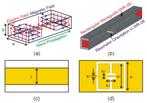
The signals in the range of 3.0-4.5 GHz shown in Fig. 1(a) are subjected to reception, amplification and down-conversion.
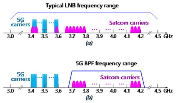
Radio regulations and licensing conditions, based on standard (NR) 5G carriers are mainly in the 3.4-3.6 GHz band and are still within the input frequency range of the LNB.
The power level of the 5G carrier may be much higher than the received GEO satellite signal, thus causing the following three types of interference to the satellite receiving system:
Type of interference
- Co-channel interference: satellite carriers within the 5G carrier bandwidth are subject to interference;
- Adjacent channel interference: The adjacent frequency band of the satellite carrier and the 5G carrier is interfered by the 3rd Order IMD, intermodulation and out-of-band spurious emissions of the 5G spectrum;
- LNB saturation interference: The high-power 5G carrier makes the LNB operating point to saturation or nonlinear state, and the received C-band satellite carrier signal suffers distortion.
Solutions
- Co-channel interference can only be resolved by rearranging satellite carriers into other frequency bands, or limiting the 5G transmit power to be sufficiently low compared to satellite carriers in the same frequency band (eg, setting a large disabled area around the satellite earth station) .
- Add a band-pass filter to the LNB input
- Add a band-pass filter to the LNB input
An ideal way to eliminate 5G interference is to install a band-pass filter at the LNB input to protect the satellite carrier in the pass band while isolating the 5G carrier outside the pass-band (Figure 1(b)).
After using the 5G band-pass filter, the 5G carrier transmitted by the adjacent channel cannot easily make the LNB saturated or deteriorate.
However, in fact, the design and production of such a BPF is not an easy task. The insertion loss of the filter passband increases the total noise temperature of the receiving system and reduces the link margin.
At the same time, the out-of-band isolation level determines the distance that the satellite earth station and the 5G base station can coexist.
The in-band and out-of-band characteristics of the filter need to be trade-off. The higher the out-of-band isolation, the greater the in-band insertion loss.
In addition, the 5G bands in different countries may be different. For example, China uses 3.4-3.6 GHz, while in the Middle East and some Gulf countries, it may be up to 3.8 GHz.
Dolphmicrowave has carefully studied the characteristics of 5G RF signals in different countries and regions and developed a series of technical specifications for filter design.
Simulating different environmental conditions, testing in the laboratory with simulation and firmware, and actually using satellite antennas and 5G base stations, the characteristics of the filters were also verified in various field environments.
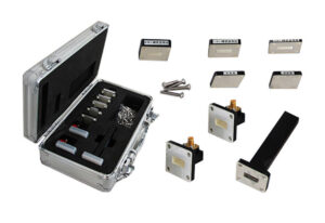
C-Band Band-Pass Waveguide Filter
DolphMicrowave’s BPF design balances in-band and out-of-band performance requirements for most C-band earth stations affected by 5G interference. especially for earth stations that have insufficient link margins and have to coexist with nearby 5G base stations.
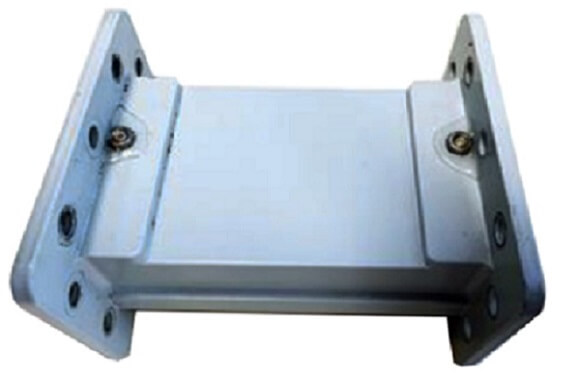
- MODEL: DH-40WBPF
- Frequency Range: 3.7 to 4.20 GHz (Options ext. C-band)
- VSWR: 1.2 : 1 max.
- Insertion Loss: 0.4 dB max.
- Rejection:
- 25 dB min at 3.65 GHz and 4.25 GHz
- 60 dB min at 3.55 GHz and 4.35 GHz
- 70 dB min at 3.5 GHz and 4.4 GHz
- Waveguide Flange CPR-229G (input), CPR-229F (output)
- Dimensions (L x W x H) 120 mm x 100 mm x 70 mm
- Weight < 500 g