Table of Contents
Frequency Range
When selecting an antenna, users must take into account the frequency range, which determines the range of the antenna’s proper operation among distance and environment. Using the example of radio frequency, the frequency range is the frequency that the antenna can cover. Usually, an antenne relates to Wi-Fi within 2.4 GHz to 5 GHz. It is important because a household router can emit the signal of same frequencies throughout the house. For example, in amateur radio, people have to communicate using the specific frequency band. Frequencies start from 1.8 MHz to up to 30 MHz, typically for long-distance communication. From a practical standpoint, the antenna has to be bigger and more spaced out for lower frequencies. It is also generally cheaper, while higher frequencies are used in urban areas and smaller in size.
For mobile communications, in the case of an LTE band, the same example would include between 700 MHz to 2600 MHz. In the scenarios where antenna frequencies do not match, the phone and tower will have the worst connection. Users will have the worst connectivity in the area, and, therefore, to maintain the signal, the device will consume a lot more power. For instance, if a user is in an urban area, their phone’s range is best on 2600 MHz band, used in the city. However, if on a trip to a village, they do not change it to 700 MHz band, their phone will experience massive drop-offs. From a practical standpoint, if the user’s satellite car antenna range is 2.3 GHz, they will always have the satellite in range wherever their location may be.
Gain
For an optimized directionality and signal strength, a user has to select the antenna with the proper gain. The latter measures the amount of energy concentrated in one direction and compares it with the energy an isotropic antenna would concentrate at the same point. The results are presented in dB, a dimension used for measuring power levels.
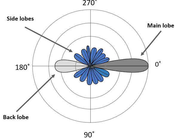
Thus, in a standard house-wireless scenario, a user might need to cover a medium-sized house, and a 5 dB gain will be sufficient. If a property is larger, and there are a lot of trees nearby, the user might opt for a 9 dB one to be comfortable by living on any part of his property. The gain affects the beamwidth of the antenna and, thus, the transmitting and receiving direction. The higher the gain, the more concentrated energy, and the narrower the beamwidth.
Speaking of a camping ground as an example of a possible experience, it is important that one communicates and, thus, perceives his or her environment even if parts of it expand kilometers away. Thus, it is essential that campers have high-gain antennas, such as a 12 dB Antenna, to ensure that a temporary relay located on a hill and transmitting information to a base camp is powerful enough to reach a few kilometers.
Similarly, an urban scenario also requires a balance gain setting since it has to expand as much as possible and, simultaneously, avoid disturbances in other people’s wifi reception. Thus, high gain might be equally harmful as low one.

Polarization
The role of polarization is one of the fundamental variables on which the design of an antenna is based. It refers to the way antennas either receive or transmit electromagnetic waves. The primary types of polarization are linear, such as horizontal and vertical, and circular, particularly right-hand and left-hand. Appropriate selection will ensure that the antenna has an optimal speech ability to travel with the orientation of the corresponding signal, leading to minimized interference and maximal signal strength. Consider a home Wi-Fi system. Most wireless antennas are vertically polarized. It is appropriate because the vertical polarization better penetrates the floors and aisles of a house. By contrast, horizontal polarization is likely to be a better choice if the same system has to work in the office of a multinational corporation covering a wide area but a sizeable flat area.
For a vast amount of communication systems, such as satellite broadcasting, usage of circular polarization is natural. It ensures that the signal is not affected by the spin of the Earth. For example, even though a satellite may wobble in the sky if left unnoticed, most satellite TV is transmitted via a right-hand circularly polarized antenna. It does not matter whether the geostationary satellite is standing on its head or feet, RHCP will always ensure that the pictures are of the highest possible quality.
It is important that the polarization of the antenna is matched with that of the signal transmitted. Mismatch can result in significant losses of the signal. For example, if a vertical polarization antenna is to receive horizontal polarized signals, the losses might be as high as 20 dBs, thus bringing the intensity of the received signals to one-hundredth of the original power.
VSWR (Voltage Standing Wave Ratio)
VSWR, which stands for Voltage Standing Wave Ratio, is obviously one of the most important factors to be taken into account while selecting an antenna, because it directly points out the quality of this equipment’s matching factors to the transmission line and the particular device. The perfect value to be described with the help of VSWR will be 1:1, while there will be no reflected power and the whole transmitter power is irradiated efficiently with the help of the antenna. Acceptable VSWR values may range from 1.5:1 to 2:1, while the lower ratio point towards the more effective power transmission. However, talking about the communication systems and dealing with their setup and maintenance one should be able to apply some effort in relation to VSWR control and manipulation, because this will be extremely important for the whole system to function and be efficient.
In other words, while setting up a communication system to be applied for the purposes of high-frequency trading it will be extremely important to take into consideration the implications of channels with smaller signals of latency, where even the smallest VSWR of 1.3:1 is unacceptable due to ridiculous transmission of data density and speed. For the VSWR to increase to 1.8:1 one might expect the increased amount of power to be irradiated back to the system, meaning that the signal released to the market will be much weaker and the whole device will be in a far inferior position and inefficient.
On the other had, if talking about the outdoor wireless communication, which is supposed to be applied in the form of radio base station, the VSWR should be carefully measured and controlled in the sake of outdoor conditions the system should be able to withstand. In this instance, VWSR would also be of extreme importance because the increased levels of this measurement value will mean the improperly taken levels of power delivery from the system, meaning that total efficiency will be diminished and the operational expenses will rise in order to keep power consumption to an admissible minimum. It should be taken into consideration that in any of the aforementioned cases one should measure the VSWR levels in order to take action and manipulate them in the event of new equipment installation on the preexistent antenna system, or in the cases of the connection systems and alignment of the antennas being heavily compromised by all sorts of natural events and weather conditions.


