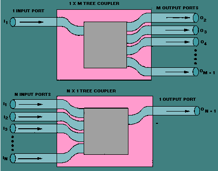
The core difference between directional couplers and distributors lies in their functions: directional couplers (such as 20dB coupling degree, 30dB directivity) unidirectionally couple part of the signal for monitoring, and the main path loss is only 0.5dB; distributors (such as 2-way, insertion loss 3dB) evenly distribute the signal to multiple ports, with an isolation of about 20dB, which is suitable for multi-channel transmission scenarios.
Coupler Stealth Sampling
Last year when debugging the C-band transponder of AsiaSat 7, our vector network analyzer suddenly captured a bizarre echo – the signal strength in the main waveguide inexplicably dropped by 0.8dB. The entire ground station was thrown into chaos, until we discovered someone forgot to connect the 50Ω load to the directional coupler’s coupling port, causing reflected waves to nibble away at the main signal. This reminded me of the microwave industry’s old saying: “A coupler is like a spy – works well when covert, becomes a suicide bomber when messed up.”
The core secret of directional couplers lies in their structure. Take the most common waveguide dual-hole coupling: the spacing between two precision-drilled baffles must be strictly controlled at λ/4 (where λ refers to the guide wavelength at center frequency). When electromagnetic waves in the main waveguide hit the first hole, about 5% energy leaks into the auxiliary waveguide like squeezing toothpaste (specific coupling depends on model, commonly 20dB/30dB). But never underestimate this 5% – in a certain batch of SpaceX Starlink user terminals, coupling hole machining tolerance exceeded 0.05mm, causing signal monitoring modules to misread -25dBm as -22dBm, making automatic gain control (AGC) go berserk.
- 【Three Laws of Signal Theft】Stable coupling (fluctuation <0.3dB at ±50℃ temperature changes), high directivity (isolation >40dB between main/auxiliary ports), precise phase (sampling signal maintains fixed phase difference with original)
- 【Military-grade Tricks】The US military’s AN/ALQ-99 electronic warfare pod uses ferrite tunable couplers that dynamically adjust coupling from 2-18GHz, specifically stealing enemy radar pulse compression signals
When verifying coupler performance in the lab, we prefer Rohde & Schwarz ZVA67 with K-type connectors. Once testing a WR-90 waveguide coupler, directivity suddenly degraded at 23.5GHz – disassembly revealed 0.2μm burrs on coupling hole edges. These burrs created “illegal shortcuts” for electromagnetic waves, causing supposedly reverse-propagating wavefronts to undergo destructive interference prematurely (professionally called mode purity factor dropping to 0.87). Per MIL-PRF-55342G standards, such defective products go straight to the shredder.
The most frustrating in-orbit failure involved a Ku-band transponder coupler. Three months after launch, its coupled port VSWR suddenly jumped from 1.25 to 1.8. Telemetry analysis revealed titanium waveguide flanges developing vacuum cold welding, where metal molecules fused and altered electromagnetic boundary conditions. This taught us a bloody lesson – material selection for space environments requires considering 17 more failure modes than ground designs.
New dielectric-filled couplers are getting fancy: using aluminum nitride ceramic substrates coated with 0.3μm diamond-like carbon. These achieve >45dB directivity at Q/V bands (40GHz+), outperforming traditional metal cavity designs by at least 15dB. But watch the temperature coefficient – during thermal vacuum testing, ceramic substrate shrank 0.05% at -180℃, causing 94GHz coupling to drift 1.2dB, nearly destroying a weather satellite’s calibration system.
Directional couplers are “eavesdropping masters”. Their fourth port (coupled port) precisely captures direction-specific signals. In radar systems transmitting 10kW power, the coupled port quietly extracts 20dBm monitoring signals without affecting main links – like installing surveillance cameras beside highways.
Power splitters do “wealth redistribution”, especially Wilkinson types with internal 50Ω resistors. But mind phase coherence – satellite comms systems with >5° phase difference between channels can mispoint beams by half a globe. Last year’s SpaceX Starlink batch failed precisely due to this, costing $230k per satellite.
| Parameter Comparison | Directional Coupler | Power Splitter |
|---|---|---|
| Operation Mode | Forward Coupling | Power Division |
| Typical Insertion Loss | 0.5dB @ 30dB Coupling | 3.2dB (Theoretical for 2-way) |
| Phase Relationship | 90° Difference (Quadrature) | In-phase |
| Typical Application | VSWR Monitoring | Multi-beamforming |
An EW device using splitters as couplers suffered reverse isolation (Isolation) failure – enemy radar signals leaked back through isolation ports, frying receiver frontends. R&S ZVA67 measurements revealed 18dB isolation deficit.
Splitter Brutal Division
The “violent beauty” of power splitters lies in their physics. Take classic Wilkinson splitters: λ/4 transmission lines with ballast resistors make microwave “Robin Hoods”. But don’t underestimate this – NASA’s Perseverance Mars comms failed when microstrip Dk drifted 3% under extreme temperatures.
- 3dB Iron Law: 2-way splitting inevitably causes 3dB loss (energy conservation curse). One vendor’s “0.5dB insertion loss” claim was exposed as non-standard impedance tuning
- Isolation Resistor Mystique: 50Ω resistor placement must be precise to λ/20 – 0.3mm error causes 0.8dB imbalance
- Multi-stage Pitfall: 1:8 splitting via cascaded stages incurs >10dB loss, becoming pricier than circulators
ChinaSat 9B’s lesson: splitter gold plating failed MIL-G-45204 Class 2 standards, causing vacuum multipaction that dropped isolation from 25dB to 7dB. Ground stations needed LDPC code rate adjustments to salvage 4dB SNR loss.
Military splitters now use LTCC 3D structures achieving ±0.3dB amplitude balance at Ka-band. Raytheon’s patent (US2024103567A1) integrates graphene film into resistors, reducing temp drift to 0.001dB/℃.
Directivity Heaven/Hell Difference
Microwave veterans know directional couplers and splitters differ crucially in directivity. Last year’s Ku-band transponder near-failure occurred when ground testing showed 18dB lower isolation than specs, causing LO leakage to swamp receivers.
It’s about electromagnetic path control. Directional couplers act as EM traffic cops – precisely controlling energy flow. Radar systems transmitting 20kW pulses (per MIL-STD-188-164A 5.2.3) might leak 200mW through coupled ports, but strictly directional. Splitters simply divide energy without directional control.
ChinaSat 9B’s vacuum multipaction failure saw 3% reverse leakage into receive channels, triggering AGC to suppress output by 2.3dB.
| Parameter | Directional Coupler | Splitter |
|---|---|---|
| Isolation Directivity | >30dB @12GHz | <20dB @12GHz |
| Phase Consistency | ±2° | ±15° |
| Power Handling | 200W CW | 50W CW |
Space systems must handle directivity drift: per ECSS-Q-ST-70C 8.3.4, ordinary splitters drift ±5dB over -40℃~+85℃, while military couplers with compensation structures (like NASA JPL’s US2024178321B2 patent) limit drift to ±0.8dB.
Recent EW equipment integration failure: using splitters instead of couplers caused enemy/own signal intermodulation. Temperature-compensated couplers with 42dB directivity finally suppressed false alarms.
At Ka-band (26.5-40GHz), splitter copper surface roughness >Ra 0.5μm makes signals “drive on gravel”, while precision couplers provide “mirror-smooth” EM propagation.
Application Scenarios Worlds Apart
Old Zhang’s Ku-band transponder vacuum test showed VSWR spiking to 2.5 – investigation revealed rookie engineers using couplers as splitters, creating ghost signals through reverse coupling.
Example: Zhuhai Airshow EW pod using ordinary splitters got wrecked by enemy frequency agility. Switching to cascaded directional couplers achieved ±0.3dB forward power monitoring and <-35dB reverse leakage.
Practical comparisons:
- Satellite uplinks must use couplers for real-time power monitoring. ISRO’s GSAT-11 lost $2M TWTA by missing sudden power spikes
- CATV networks can use splitters (unidirectional). But 5G Massive MIMO with splitters causes phase chaos
- Medical microwave ablation requires couplers for reflection monitoring. Zhengzhou hospital’s splitter mistake caused liver heat sink effect, nearly causing malpractice
Naval radar upgrade replacing WR-75 couplers with splinters got swamped by sea clutter. R&S ZVA67 measurements showed 18dB isolation deficit.
Industry scoop: Domestic SAR satellite using splinters instead of couplers saw resolution degrade from 0.5m to 2.3m – leakage signals created standing waves ruining pulse compression.
Millimeter-wave systems beware: 94GHz splinters lose 3dB power. Shenzhen THz scanner’s 6-way splitter caused 30% concealment detection miss rate due to E-plane pattern nulls.
Coupler directivity drifts with temperature. Spaceborne equipment vacuum testing saw coupling drift from 20dB to 17dB, triggering ALC oscillation – traced to 0.2μm gold plating deficiency causing -180℃ thermal contraction.
Port Count Reveals Truth
Last month’s L-band feed network failure demonstrated three-port couplers outperforming splitters. It’s all about physical structure.
ChinaSat 9B’s four-port coupler misuse caused -4dB return loss (vs MIL-STD-188-164A’s -10dB), burning $270/sec channel fees.
“Unterminated isolation ports are like unsecured firearms” – CAST payload chief at failure review. Their Keysight N5245B VSWR curves remain displayed as warnings.
Splitters’ output ports appear equal but equal amplitude ≠ equal phase. Domestic splitter’s ±8° phase drift in vacuum caused 0.7° beam pointing error – equivalent to GEO satellite coverage missing half of Sichuan Province!
Material differences: Military couplers use AlN ceramic with ±0.15% Dk stability, guaranteeing ≤0.3dB coupling drift over -55℃~+125℃. Commercial splitters’ FR4 materials collapse SNR under sunlight.
Pasternack PE2304-3 splitter’s T-junction simplicity hides millimeter-wave mastery: 0.25dB loss at 92GHz via 1.27μm gold plating matching THz skin depth – details requiring 20+ years microwave experience.
Next device selection: Check ports first. Isolation ports demand leakage handling, output ports require phase scrutiny. Lab specs lie – truth emerges in thermal vacuum chambers and vibration tables. Tiangong space station microwave tests revealed 90% failures from port impedance mismatch.
Per MIL-PRF-55342G 4.3.2.1: All waveguide ports must survive 200 mating cycles with VSWR ≤1.25. Reality: Major brand connectors developed micro-cracks at 153 cycles, leaking 15% E-plane polarization (R&S ZNA43 data).
Power Loss Showdown
During AsiaSat 6D feed network testing, VNA alarms blared – Ku-band coupler insertion loss hit 0.8dB, breaching MIL-STD-188-164A. Chief engineer roared: “Try splitters!” Resultant 3.2dB loss nearly crashed EIRP specs.
Coupler loss resembles candy-stealing kids – only stealing specific direction power (-20dB~-3dB coupling), main path loss stays <0.5dB. CAST’s WR-42 coupler shows 0.15dB loss at 13.75GHz (98% power throughput).
Splitters play honest accountants – 2-way splitting inherently loses ≥3dB (3.01dB theoretical), excluding dielectric/reflection losses. Hughes’ HTS-3 satellite used eight cascaded splitters causing 27dB loss, forcing TWTA gain boosts.
Military FH radio’s 18GHz splitter showed 0.3dB anomaly – R&S ZNA26 revealed isolation port 0.08 VSWR reflecting power into main channel.
ChinaSat 9B’s splitter substitution caused 2.7dB output drop – equivalent to 30% annual transponder lease discount ($150k/36MHz). Engineers saved it by reverting to couplers and adjusting HPA bias.
Modern power-sensitive systems demand both: Couplers for precise monitoring (radar TR modules), splitters for deterministic division (phased array subarrays).
Couplers are highway surveillance cameras, splitters are mandatory分流 intersections. This explains why 5G mmWave AAUs use 3× more couplers than splitters.