The design procedure for a slotted waveguide antenna utilizing standing waves. Notably, The use of electromagnetic (EM) solvers for computing slot design curves, a departure from the previous empirical approach employed by Robert Stegen. The adoption of EM simulators lends greater flexibility to the design process, enabling more precise and efficient iterations. Consequently, the article highlights the significance of utilizing EM solvers for the design of slotted waveguide antenna arrays.
When evaluating slot admittance and resonant length versus angle or offset, there are several methods available. One approach is the use of EM simulators, which provide increased flexibility in the design process. EM simulators allow for accurate and detailed analysis of the electromagnetic behavior of the slots, enabling engineers to assess the admittance and resonant length variation with different angles or offsets. These simulations offer a virtual environment where the parameters can be adjusted and analyzed to optimize the slot design for specific requirements. By utilizing EM simulators, engineers can gain valuable insights into the performance characteristics of slots under different conditions, aiding in the evaluation and refinement of slot admittance and resonant length with respect to angle or offset.
Yes, there are current experts in the field of waveguide fed slot arrays. One such expert is Sembiam Rengarajan, who is a Professor at Cal State Northridge. Professor Rengarajan has extensive experience in this area, having previously worked for Elliott while at Hughes. He has made significant contributions to the field, including publishing an update on waveguide fed slot arrays as recently as 2010 at the IEEE APSURSI conference. In his publication, titled “Advances in waveguide-fed slot arrays,” Professor Rengarajan provides an overview of the state-of-the-art in this field, showcasing his expertise and knowledge on the subject.
The design procedure for a standing wave fed array with slots in the narrow wall of the waveguide involves various steps. One crucial aspect is the computation of the slot design curves, which are depicted in Figure 1. Rather than relying on the empirical approach initially used by Robert Stegen, the authors emphasize the importance of utilizing an electromagnetic (EM) solver for this computation.
To begin, the first step is to determine the number of slots required for the standing wave fed array. This can be calculated based on the desired performance specifications and the operating frequency of the waveguide.
Once the number of slots is established, the next step involves determining the dimensions and placement of these slots along the narrow wall of the waveguide. This is a crucial aspect as the slots dictate the radiation pattern and efficiency of the array.
To achieve the desired design, The use of an EM solver. This solver employs computational techniques to accurately model and analyze the electromagnetic behavior of the waveguide. By utilizing this approach, the slot design curves can be obtained, which further aid in achieving the desired performance of the standing wave fed array.
By relying on an EM solver for the slot design curves, the authors suggest a more accurate and efficient alternative to the empirical approach originally used by Robert Stegen. This allows for a more precise prediction of the behavior of the array and enables engineers to fine-tune the design parameters to meet specific requirements.
Yes, there are acknowledgments and funding sources mentioned for the antenna manufacturing. The authors express their gratitude to ATMOS Sistemas Ltda. for providing the financing for this endeavor.
The workflow presented provides a comprehensive approach for the entire antenna project, showcasing the utilization of simulations at every stage to enhance antenna performance. By incorporating simulation techniques, the proposed workflow successfully addresses various aspects, starting from the characterization of slots to the physical prototyping of the antenna.
Throughout the workflow, simulation plays a crucial role in optimizing the design of the antenna. Through iterative simulations, the performance of the antenna with 12 slots is thoroughly analyzed, ensuring that it achieves optimum performance without any further modifications needed. This method saves time and resources by eliminating the need for unnecessary design iterations and physically testing multiple prototypes.
Furthermore, the simulation-driven workflow ensures the accuracy of the final design. The results obtained through simulations are effectively validated through the measurements of a physical prototype. This verification process provides confidence in the accuracy of the simulations and confirms that the antenna performs as anticipated in real-world conditions.
In summary, the proposed workflow significantly enhances antenna performance and accuracy. By incorporating simulation tools throughout the entire process, potential design issues are identified and resolved early on, leading to an optimized design without the need for multiple physical iterations. The accuracy of the simulations is confirmed through physical prototyping, validating the effectiveness of the workflow in achieving the desired antenna performance.

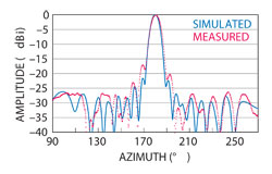
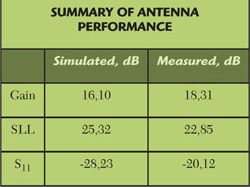
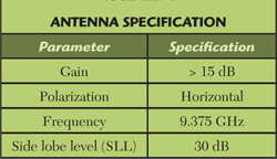
The final antenna underwent a thorough prototyping and testing process to ensure its functionality. The prototype was fabricated and subsequently tested within an anechoic chamber. Figure 2 provides a visual representation of the antenna design. It was observed that the antenna displayed a highly directional pattern in the azimuth plane, as indicated in Figure 3. Comparisons between the measurements taken and the simulated results revealed a close agreement, albeit with some variations that can be attributed to the measurement setup. As the antenna was mounted on a metallic mast, the mast itself potentially interacted with the electromagnetic fields, influencing the results to some extent. These findings and observations regarding the antenna’s performance have been summarized in Table 1.
The simulated radiation pattern, when compared to the theoretical pattern, shows that the highest simulated side lobe is within the theoretical main lobe. This suggests that the simulated pattern is a modulation of the theoretical main lobe and not a true secondary lobe. Despite this, it should be noted that the simulated pattern cannot be fully mitigated unless modifications are made to the slot geometry. Therefore, while the simulated pattern closely resembles the theoretical one in terms of the main lobe, there is still room for improvement by adjusting the slot geometry.
The antenna design is evaluated using CST STUDIO SUITE software. To achieve convergence quickly, a dummy object made of vacuum is used to fill the slots in the antenna design. This allows for local refinement to be directly applied to the slot volume. The evaluation process involves simulating the antenna with the F-solver and validating the results using the time domain solver (T-solver). Adaptive meshing and local mesh refinement techniques are applied specifically to the slots during the simulations. By comparing the far field results obtained from both the F-solver and T-solver, we can ensure the accuracy of the simulation. This involves carrying out two simulations using different numerical methods and meshes. The results from these simulations are then summarized in Table 2, providing an overview of the antenna characteristics.
To evaluate the required admittances for the final antenna, the first step involves considering the excitation of each individual element. Once the elements are taken into account, the next step is to derive the required normalized conductances (gn) using a set of equations. These equations play a crucial role in calculating the admittance values necessary for optimizing the performance of the antenna. Through this evaluation process, the desired admittances required for the final antenna configuration are determined, ensuring efficient and effective operation.
The antenna synthesis procedure involves several key steps to design and optimize the performance of an antenna. These steps are as follows:
- Define the Array Function: The process begins by determining the Taylor polynomial that represents the desired array function. The parameters such as the desired side lobe level (SLL), the number of elements in the antenna array, and the number of side lobes are considered as inputs for this step.
- Determine Individual Excitations: Using the defined array function, the antenna excitations for each slot or element are calculated. These individual excitations (an) are obtained through MATLAB simulations or calculations.
- Analyze Design Curves: The curves generated through MATLAB are then carefully examined to identify the appropriate values for the inclination angle (θ) and resonant length (Lr) that will generate the required conductance for the antenna.
- Determine Slot Parameters: Once the design curves have been analyzed, the inclination angle and resonant length of each slot can be determined. It is worth noting that for simplicity and symmetry reasons, parameters of the remaining slots are typically the same as the first half, but in reverse order.
- Evaluate Required Admittances: In this step, the required admittances for the final antenna are evaluated, taking into account the individual excitations calculated in step 2. By considering each element’s excitation, the necessary normalized conductances (gn) are derived using appropriate equations.
By following these key steps, the antenna synthesis procedure aims to design an antenna with optimized performance, satisfying specified criteria such as side lobe level and number of side lobes.
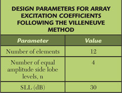
The process of antenna synthesis begins by utilizing a Taylor polynomial that represents the array function. This polynomial takes as inputs various parameters including the desired side lobe level (SLL), the number of elements within the antenna, and the number of side lobes. The output of this synthesis procedure is the individual excitations for each slot (an) within the array.
To determine the appropriate values for the parameters, the generated curves are examined using MATLAB. Through analysis, the values of ? (unknown parameter) and Lr (wavelength multiplier) are carefully assessed to ensure that they ultimately yield the necessary conductance. A summary of the input parameters for the synthesis polynomial can be found in Table 3.
To derive the null susceptance (b50) using the contourc function, a specific process is followed. The contourc function is utilized to generate a curve that represents the slice of null susceptance. This curve contains all the values of Lr (λ) required for resonance.
After obtaining this curve, the values of Lr (λ) are extracted and inserted back into the 3D model. The antenna is then re-simulated using these updated values. The simulation process is repeated iteratively until the desired accuracies are achieved. This iterative approach allows for refining the null susceptance by progressively adjusting the values of Lr (λ) in the 3D model until the desired outcome is reached.
To analyze the susceptance data in MATLAB, two different interpolation methods are employed. Firstly, the interp1 function is used with the “pchip” method to interpolate the points of susceptance as a function of the slot length for each angle. This function interpolates the data points using piecewise cubic Hermite interpolation, which ensures a smooth and continuous curve through the given data.
Furthermore, the curves obtained from the above interpolation step are interpolated in an additional dimension using the interp2 function. This function adopts the “cubic” method to interpolate the curves in the specified dimension, resulting in a smooth and accurate representation of the data. The “cubic” method utilizes piecewise cubic interpolation in two dimensions, considering both the slot length and angle variables to interpolate the curves.
By utilizing these specific interpolation methods, MATLAB enables the analysis and evaluation of the susceptance data with high precision and flexibility.
The purpose of the parameter sweep in antenna design is to determine the optimal geometrical parameters that will result in null susceptance. By performing a parameter sweep, a set of admittance points is obtained, which need to be evaluated in order to identify the best possible geometrical parameters. This process helps in constructing a susceptance surface.
To find the slice of null susceptance (b50), the contourc function is utilized. The contour represented by this function contains the necessary values of Lr (λ) that are necessary for resonance. These values are then integrated back into the 3D model, and the antenna undergoes re-simulation.
In summary, the parameter sweep helps in identifying the most suitable geometrical parameters for an antenna design by generating a set of admittance points. This information is then utilized to construct a susceptance surface and identify the slice of null susceptance, ultimately leading to the refinement of the antenna’s 3D model for improved resonance performance.
During the evaluation process for the synthesis of each slot in an edge-slotted waveguide antenna, two important curves are derived. The first curve obtained is the relationship between the slot inclination and the required slot conductance. This curve helps determine the proper slot inclination for achieving the desired level of slot conductance.
The second curve derived is the correlation between the slot resonant length and the slot inclination. This curve assists in determining the appropriate slot resonant length based on the chosen slot inclination.
Both of these curves are crucial in the design of edge-slotted waveguide antennas, as they provide valuable information for the synthesis of each individual slot. By utilizing these design curves, engineers and designers can optimize the performance of the antenna by accurately determining the necessary slot inclination and length for achieving the desired objectives.
The resonant length (Lr) and slot inclination angle (Θ) for each slot in the antenna are evaluated using a parameter sweep and the frequency domain solver (F-solver) of CST MICROWAVE STUDIO.
To account for the mutual coupling effect, the simulation considers an array of N identical slots rather than a single slot. This approach is more realistic and provides a better understanding of the overall performance of the antenna.
During the parameter sweep, the slot depth (d) is adjusted to find the resonant length (Lr) of the slot at each angle (Θ). The resonance is determined when the normalized susceptance (b) of the de-embedded waveguide port to the center of the first slot becomes null.
The computed admittance at the waveguide port is assumed to be the product of the number of slots and the normalized slot admittance. This allows for the determination of the required slot conductance and the resonant length of the slot for each slot inclination angle.
By the end of this process, two important curves are derived: the slot inclination angle versus required slot conductance, and the slot resonant length versus slot inclination angle. These curves serve as the design guidelines for the synthesis of each slot in an N-edge slotted waveguide antenna.
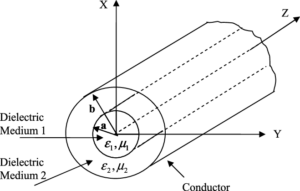
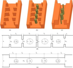
In the design of individual slots, there are several important parameters to optimize. The choice of waveguide, such as the WR-90 type, along with the milling equipment, determines certain fixed parameters including ‘a’ (width of the waveguide), ‘b’ (height of the waveguide), ‘w’ (width of the slot), and ‘t’ (thickness of the slot). This leaves two independent parameters, namely the slot inclination angle (‘θ’) and the depth of the slot (‘d’), to be optimized.
It is assumed that the complete length of the slot is measured on the internal face of the waveguide, denoted as ‘Lr’. This length, with a resonant length designated as ‘Lr = 0.4625 λg’, plays a significant role in the optimization process.
To specify the gain, side lobe level (SLL), and beam steering of the slotted waveguide antenna, engineers have the flexibility to choose an array type and its setup. One commonly used array type is the discrete Taylor distribution, which offers several benefits in achieving the desired specifications. The discrete Taylor distribution allows for a smooth variation between the excitations of adjacent elements, which is particularly advantageous when concern for mutual coupling arises. Additionally, this array type provides a good theoretical match to the SLL requirement. By distributing the slots along the waveguide in an array configuration, engineers can effectively control the gain, SLL, and beam steering characteristics of the slotted waveguide antenna.
Edge-slots are designed to achieve resonant length through a systematic process that takes into consideration various factors. Typically, the design of edge-slots does not consider the mutual coupling between slots or the thickness of the waveguide. However, to ensure accurate analysis and optimal performance, it is essential to consider these effects.
An accurate analysis of the antenna design should include the influences of mutual coupling, waveguide thickness, coaxial transitions, and flanges. This is where electromagnetic (EM) simulation comes into play. EM simulation enables the modeling of these effects, effectively replacing the traditional empirical trial-and-error method with a computational evaluation.
The design process begins by characterizing the individual slots, where several important parameters come into play. The choice of waveguide and milling equipment determines certain parameters such as the dimensions of the waveguide, including its width (w), thickness (t), height (a), and length (b). These dimensions leave only two independent parameters to optimize: the slot inclination angle (θ) and the depth of the slot (d).
The overall slot length is assumed to be resonant at the operational frequency, and it is determined by the length measured on the internal face of the waveguide. This length, known as Lr, is considered resonant when Lr = 0.4625 times the guide wavelength (λg) for the central frequency of interest.
To evaluate the resonant parameters, such as the slot resonant length (Lr) for a given slot inclination (θ), a simulation is performed considering the effect of mutual coupling. Instead of simulating a single slot, an array of N identical slots is simulated for each angle. This approach provides a more realistic representation since it accounts for the influence of mutual coupling.
To find the slot’s resonant length (Lr), a parameter sweep is conducted for each angle (θ). The depth of the slot (d) is adjusted in the simulation until the normalized susceptance (b) of the de-embedded waveguide port to the center of the first slot becomes null, indicating resonance. The computed admittance at the waveguide port is then assumed to be the product of the number of slots and the normalized slot admittance.
Throughout this process, two crucial design curves are derived: the relationship between slot inclination and required slot conductance, and the relationship between slot resonant length and slot inclination. These design curves serve as valuable tools in the synthesis of each slot in an N edge-slotted waveguide antenna, ensuring that the resonant length is achieved for optimal performance.
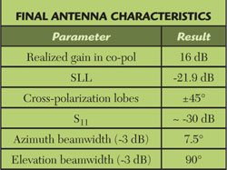
The design requirements for a naval radar antenna operating in X-Band (8 to 12 GHz) include the following specifications. Firstly, the antenna must have a narrow beamwidth in the azimuth plane to ensure precise scanning capability. This enables the radar to accurately detect and track targets in the horizontal direction. Secondly, the antenna should have a wider beamwidth in the elevation plane in order to compensate for the roll of the ship. This compensates for the ship’s movement and ensures proper coverage in the vertical direction.
In addition to the beamwidth requirements, other parameters are also specified in Table 4. These parameters may include aspects such as gain, power handling capability, polarization, and size restrictions. These specifications are crucial in order to meet the naval radar antenna’s operational needs and ensure optimal performance in the designated X-Band frequency range.
The virtual design of a slotted waveguide antenna is thoroughly analyzed and designed in this article. The slots are strategically placed on the narrow wall of the waveguide. To validate the effectiveness of the virtual design, two different numerical methods and various mesh types are employed to create simulations. These simulations are then compared to both the analytical solution for array antennas and the performance of a physical prototype.
By utilizing the power of computer simulations, the virtual design offers a comprehensive workflow for the analysis and design of the slotted waveguide antenna. The simulations enable a detailed examination of the antenna’s performance and characteristics, providing valuable insights that would be otherwise challenging or time-consuming to obtain through traditional analytical methods.
To ensure accuracy and reliability, two distinct numerical methods are employed to simulate the virtual design. This approach allows for a comparative analysis of the results obtained from different simulation techniques. Additionally, the use of various mesh types further enhances the accuracy of the simulations, leading to more precise predictions and evaluations of the antenna’s performance.
To assess the validity of the virtual design, the simulated results are compared to both the analytical solution for array antennas and the performance of a physical prototype. This comparison serves as a benchmark to evaluate the accuracy and efficacy of the virtual design. By aligning the simulated results with the analytical solution and the physical prototype performance, any discrepancies or variations can be identified and analyzed.
Overall, the article aims to determine how the virtual design of the slotted waveguide antenna compares to both the analytical solution and the performance of a physical prototype. By conducting simulations using different numerical methods and mesh types, and subsequently comparing them to well-established solutions, the authors provide in-depth insights into the virtual design’s efficacy and its potential real-world performance.
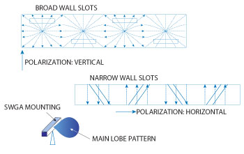
The polarization of the fields in an antenna design is dependent on the placement of slots. When longitudinal slots are positioned on the broad wall, they generate a field with vertical polarization. Conversely, if transverse slots are placed on the narrow wall, they produce a field with horizontal polarization. Therefore, the orientation of the slots in relation to the walls of the antenna directly affects the polarization of the resulting fields.
Slotted waveguide antenna (SWA) are widely utilized in radar applications that necessitate high gains and mechanical robustness. They serve as a practical alternative to planar arrays due to their ability to handle the peak power transmitted by radar antennas, which is typically of very high magnitude. SWAs are particularly suitable for scenarios where design specifications call for both efficient transmission and structural durability.