The IEC standard for waveguides specifies dimensions, materials, and testing protocols for optimal performance and compatibility.
Table of Contents
Classification of Waveguides According to IEC Standards
Rectangular Waveguides
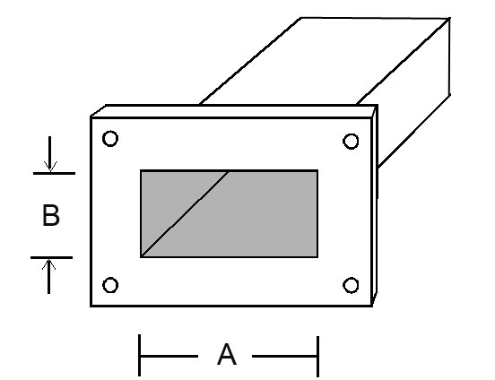
Rectangular waveguides represent one of the main types of waveguides used in microwave transmission around the world, and the trope of their name is tied to the very nature of their operation – that is, their shape . If one waveguide can support a single mode of propagation, any of the rectangular variants will provide the same function and more, ensuring that many such variants can be found in high-precision machinery. However, an important part that supplies the required electromagnetic field and is built in from silicon substrates and efforts is proportional to in integrated optics is a difference in modes, which results in certain construction and causes a decrease in their quality to purpose-built multi-module integrated chips .
Material and Dimensions
For the most part, even though these waveguides are formed either from aluminum for lower frequencies or copper and the internal dimensions of importance are relatively arbitrary, or custom as are others. A common standard can be a choice for a 0.0×0.0x-mm rectangular waveguide operating from 8 GHz to 12 GHz – that is, small enough for its size to be considered in all practical purposes . Notably, these decisions are made with waveguide efficiency in mind because power loss is the most important parameter in radar and satellite applications and should be kept as low as possible. Power handling is also significant, and there is a standard waveguide that will handle around 150 kW. The cost is on a case-by-case basis, but copper waveguides are generally 20% more costly and have 15% more power handling capabilities. Circular Waveguides
Circular waveguides are a widely-used category of waveguides, which mainly find purpose in transmission machines where the waveguide must be redirected at an angle. Because of their circular ridges, this type of waveguide can support multiple modes of propagation, which can also be useful for a wider range of frequencies. The main advantage of these waveguides is their higher rate of handling, and they are most useful in systems where they can be used to direct the waveguide around obstacles with little loss in quality – a circle model can be a typical variant in an airport radar system.
Flexible waveguides are becoming more and more demanded in the industrial sector for their unprecedented advantages. Thus, the primary technical advantage of the waveguides is the prospect of bending. Thus, the waveguide consists of a copper spiral, which means that it can make a bend at the user’s discretion. Of course, an ideal system does not exist, and the technical characteristic of the waveguide stipulates that the maximum input power does not exceed 1 – 1.5 kW. It is essential to note that such a relatively low efficacy value was considered a crucial advantage when choosing the waveguide. Therefore, the second advantage that is directly related to versatility is the chance of using multi-mode transmission. The materials from which the flexible waveguide is made include silver-coated copper, which is considered to be of the highest purity . It means that the waveguide can be effectively used for making twists necessary in space-constrained circumstances. . Finally, due to quality work in terms of electromagnetic welding, the flexible waveguide will not fail for at least 10 years through the use of relevant resources. Therefore, it can be safely stated that this product will serve for at least the indicated period of time.
Technical Specifications in IEC Standards for Waveguides
Dimensional Tolerances
Dimensional tolerances are crucial for waveguides to work appropriately on their designated frequency. IEC standards are strict as they dictate precise tolerances that guarantee the fidelity of signal transport.
Inner Dimensions and Tolerances
A rectangular waveguide designed to operate on the X-band would have its internal width dictated by the IEC standard to be within ±0.1 mm and height would be within ±0.1 mm. This high level of precision ensures that the mode distortion is prevented, as it may cause substantial power losses and risk failure of the waveguide.
Circular waveguides are no different and their diameter tolerance is similarly within ±0.1 mm, regardless of the application, whether it may be telecommunications or radar systems.
Material Specifications
The material used will dramatically influence the efficiency, power capacity and lifecycle of a waveguide. IEC standards offer robust guidelines on material selection for a given purpose.
Conductivity and Material Types
Copper is selected for its superior electrical conductivity in high-efficiency applications. For instance, to reduce the power losses of a waveguide operating at 10 GHz the user should select copper with conductivity of 5.8×10^7 S/m – by doing so, the user can reduce the power loss by as much as 20% as opposed to aluminum . A more expensive silver or gold coating that will lower the attenuation of signal should be reserved for the most critical of applications.
Performance Criteria
These cover a wide range of criteria, such as power capacity, frequency range and VSWR.
Power Handling and Frequency Range
A standard rectangular waveguide cannot run on more than 1 kW of continuous power unless it is cased or operated in a different power setting scenario. At higher frequencies, the losses of waveguides are higher and the risk of arcing due to emitted radiation is a significant limitation. Finally, the WR-90 waveguide is an X-band waveguide with high specifications, but no other IEC standard would apply at lower frequencies.
VSWR and Efficiency
Efficiency is directly tied to low VSWR, often less than 1.05:1, such as in case of the WR-90 waveguide. This means that nearly all of the transmitted power is actually delivered to the load and not circulating in the waveguide itself. Efficient use of power is imperative in satellite communications applications and HF radar installations.
Testing and Measurement Protocols for Waveguides Under IEC Standards
-
Electrical Performance : In the area of electrical performance, tests aim to ensure that the waveguide meets or exceeds the standards for signal transmission. All values describe performance: VSWR or voltage standing wave ration, attenuation, and the power handling capability.
-
VSWR and Attenuation Measurement : When testing for high conduction grade surveilling camera, I would expect my team to measure VSWR and record the value below 1.1:1. I would expect that from a given output where VSWR for high-quality copper waveguides would be 1.05:1 . It reflects the sign of minimal reflection and perfect matching. I would also expect my team to measure a value of an attenuation of less than 0.1 dB/m at 10 GHz showing less power loss and better performance high conductivity.
-
Power Handling Capability : The waveguide should be able to pass a power to the receiving end without tripping or arcing. For that reason, it should be able to pass a power of 1kW to the receiving end continuously .
-
-
Mechanical Durability : The objective of these tests is to determine the shelf life and withstanding of mechanical force, the endurance of the bending test, vibration test, and impact test.
-
Bending and Vibration : A test will be set to find out the quality of the waveguide in bending. It may be tested by bending action to bend at a 5 cm radius. A check to ensure that the bending does not lead to breaking or significant attenuation. Vibration tests are also a form of action during transportation. Therefore, it is anticipated that the waveguide will provide better quality results with an additional loss of less than 0.05dB .
-
Impact : Tests to ensure impact will be conducted to find out the effect of an action of a falling object. Either by static or free-falling objective, the waveguide will be inspected for signs of breakage or dent marks. A high-quality waveguide without additional loss or visible dents and alteration is capable of withstanding the weight of a falling object.
-
-
Environmental Resistance :
-
Temperature and humidity : There will also be a test for temperature-resistant and humidity wardrobe. He should be able to resist temperature from -40^0 to 85°C . The team should also ensure that humidity of up to 95% of 10 days she not lead to signs of moisture retention which is followed load with corrosion.
-
Salt fog and humidity test : The test simulates the effect of a halogen fog. This test is appropriate for most maritime applications. The tested material should be able to withstand the humidity and salt flog from the ocean.
-
IEC Standards for Waveguide Connectors and Assemblies
Connector Types and Compatibility
Connector types and the concept of compatibility are crucial for ensuring that waveguide systems can be integrated into broad communication infrastructures with ease. According to the IEC system of classification, connectors are rated by design, application-specific attributes, and frequency range to simplify selection and use . The IEC standards also define which connector types can be used with waveguides. The N-type connector is a standard solution for waveguides, which is viable for applications up to 11 GHz. It is widely used for connecting waveguides to lower frequency power sources, which is important because engineers need to understand how it fits within their system. The SMA connector was also mentioned as a way of connecting the system to a higher frequency. Compatibility is crucial because it is preset by the dimensional characteristics of flanges and the material used, and is considered along with the notion of interconnectivity . Interconnection was considered within the context of VSWR control, meaning the range of values that minimize the mismatch losses in waveguide assemblies.
Assembly Techniques and Requirements
General principles of assembly are part of the IEC standards, which include the welding, brazing, and bolting techniques. The tactics may seem simple but are critical for ensuring the system’s long-term reliability in achieving a stable high-quality joint. For instance, for all waveguide assemblies that operate above the frequency of 18 GHz, the use of brazing with a filler material that has a less than liquidus melting point above 450°C is suggested. Oftentimes, it is essential to inspect requirements for mechanical fastening, often based on the common practice of using the gasket in the flange necks. A waveguide flange might need to be bolted with eight bolts instead of four, which secures the connection and ensures no air can escape through the flange. Not meeting these requirements can damage the external equipment since it introduces water, dust, and other contaminants into the waveguide. If the assembly in question needs to be taken apart, then a gasket should be used. This gasket should be made of indium or silicone, providing minimum air leakage while also integrating into the system as a whole. Meeting these requirements will guarantee that the waveguide connectors and assemblies adhere to the IEC standards, making them compatible and efficient as part of the whole system.

