+86 29 8881 0979

default

Top 6 Coupler Loops Manufacturers Market Leaders and Innovators

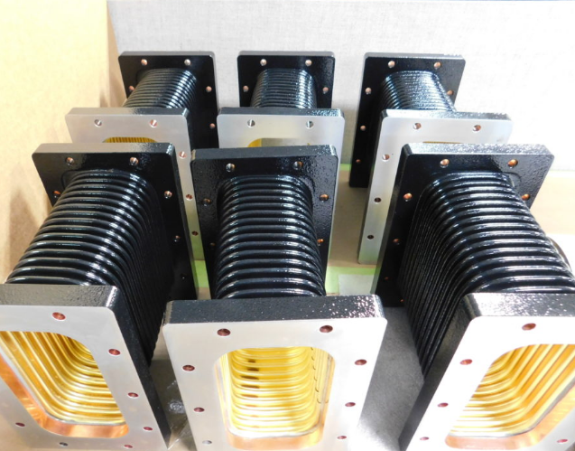
Leveraging cutting-edge technology, Dolphmicrowave, Harris Corporation, Raytheon Technologies, Northrop Grumman, L3Harris Technologies, and ViaSat Inc. are shaping the future of satellite communications with innovative coupler loops and RF solutions. In the dynamic and ever-evolving landscape of satellite communications, the quest for seamless global connectivity has given rise to a select group of manufacturers who stand […]

Top 6 Coupler Loops Manufacturers Market Leaders and Innovators Read More »

What is the frequency range of the near-field probe

The frequency range of near-field probes typically spans from 10 kHz to 6 GHz, enabling versatile applications in electromagnetic testing. Broad Spectrum Capability Near-field probes are a key instrument in the electromagnetic testing world, and they are made to effectively function over various frequencies. They range from about 100 kHz that is valuable at the

What is the frequency range of the near-field probe Read More »

4 difference between near-field and far-field antenna measurements

Near-field measurements occur within a few wavelengths of the antenna, focusing on reactive fields for design optimization. Far-field measurements, taken at distances greater than 2D²/λ, assess radiative fields for long-range performance. Distance Near-field and far-field antenna measurements differ primarily based on the actual physical distance from the antenna at which the measurements take place. Both

4 difference between near-field and far-field antenna measurements Read More »

3 differences between microwave transmission and radio wave signals

Microwaves operate from 1 GHz to 300 GHz, ideal for high-speed data links and requiring line-of-sight. Radio waves, spanning 3 kHz to 300 GHz, are better for broad coverage and can diffract around obstacles. Microwaves are used in radar and satellite communications, while radio waves are widely used in broadcasting and mobile communications. Frequency Range

3 differences between microwave transmission and radio wave signals Read More »

6 side effects of introducing corners and bends into waveguides

Introducing corners and bends into waveguides can increase signal attenuation by up to 0.1 dB/bend, necessitating larger bend radii and signal boosters for optimal performance. Reflections and Losses Making the previously mentioned changes can also substantially change the manner in which signals are transmitted through a waveguide, creating reflection and loss. Both phenomena are highly

6 side effects of introducing corners and bends into waveguides Read More »

3 differences between GSM antenna and microwave antenna

GSM antennas operate at 900-1800 MHz for mobile communications, while microwave antennas use 1-300 GHz for broadband and satellite links, requiring larger, more precise designs for longer distances. GSM Antenna GSM antennas are devices for mobile cellular communication that operate in standard frequency bands, most often in both 900 MHz or 1800 MHz. The device’s

3 differences between GSM antenna and microwave antenna Read More »

Top 5 reasons parabolic dish antennas are most commonly used in microwave applications

Parabolic dish antennas are widely used in microwave applications due to their high gain (20-40 dB), focused directivity for long-distance point-to-point communication, broad frequency range (1-300 GHz), efficiency in power use, and customizable sizes and specifications for varied applications. High Gain and Directivity One of the primary reasons why parabolic dish antennas are so popular

Top 5 reasons parabolic dish antennas are most commonly used in microwave applications Read More »

The 7 benefits or advantages of an RF waveguide

RF waveguide has seven major advantages: 1. Low loss (only 0.1dB/m at 10GHz); 2. High power capacity (supports 10kW continuous wave); 3. Anti-interference (metal enclosed structure); 4. Wide bandwidth (WR-90 covers 8.2-12.4GHz); 5. High temperature resistance (>500℃); 6. High isolation (>80dB); 7. Suitable for millimeter wave transmission, commonly used in radar feeders and satellite communication

The 7 benefits or advantages of an RF waveguide Read More »

4 steps to calculate the cutoff frequency of the waveguide

To calculate a waveguide’s cutoff frequency, first measure its dimensions, then determine the mode numbers, apply the formula 𝑓𝑐=𝑐2(𝑚𝑎)2+(𝑛𝑏)2f c​ = 2c​ ( am​ ) 2 +( bn​ ) 2 ​ , and validate the results with empirical testing. Identify Waveguide Dimensions and Mode The cutoff frequency of a waveguide can only be calculated if

4 steps to calculate the cutoff frequency of the waveguide Read More »

What 4 factors are useful to consider when comparing the relative ranges of antennas

When comparing antenna ranges, consider gain, frequency, design, and environmental conditions. Gain When it comes to antennas, gain is one of the essential characteristics that has a dramatic impact on its range and function. Gain, quantified in decibels , is a measure of an antenna’s ability relative to an isotropic one to concentrate the power

What 4 factors are useful to consider when comparing the relative ranges of antennas Read More »

Scroll to Top
Blank Form (#3)