Resonant Frequency
The resonant frequency of a dipole antenna explains a specific frequency at which the antenna operates at the maximum efficiency level. This frequency is resonance as it dictates the antenna’s functionality in transmitting and receiving the electromagnetic waves . To understand how the concept of the resonant frequency applies to a practical example, one could use a common FM antenna as a case in point. Given that this type of dipole antenna is designed to meet the needs of users regarding commercial FM radio frequency band between 88 and 108 MHz, its resonant frequency is approximately at the point of 98 MHz or the middle of the considered range. However, the crucial task is to evaluate how the chosen frequency could be at its correct point to this specific Amateur Radio 2-meter band, which should be approximately 144 MHz over which the antenna should be tuned to ensure receiving and transmitting radio capabilities.
The frequency found at the specific distance should be about halfway on the length of the dipole at a factor of 144 MHz, which could be calculated by finding the wavelength with the assistance of the formula λ = c/f. The oscillator rate is declared to be 300,000,000 meters per second , with 144 MHz being used as a frequency. Thus, half-wave resonance length would be 1.04 meters, with the ideal size of the dipole making one meter. Dipole antennas are generally used for television broadcasting needs, and in the current case, the focus could be on UHF frequency between 470 and 860 MHz. To be able to function within the framework of such variety and range, the antennas should be capable of assisted a broader bandwidth range, thus, being longer in such cases.
Radiation Pattern
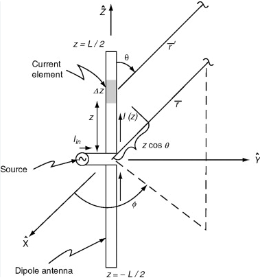
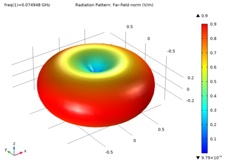
One of the most critical characteristics of an antenna related to its geometry is the radiation pattern, which describes how it distributes energy into space. Dipole antennas, a frequent variant of configuration, have a radiation pattern in the form of a figure of eight in the horizontal plane and a doughnut shape in the vertical plane. This means that a dipole antenna radiates most of its energy perpendicular to its length, with the energy radiated off the ends being almost zero . Understanding the radiation pattern of a dipole antenna is incredibly crucial for maximizing its operation points.
Some applications of dipole antennas, such as amateur radio setups, can optimize operations based on the radiation pattern. Specifically, in such environments, a user is likely aiming to maximize their communication capabilities, with distant stations to be reached in every angle of the antenna. This often implies that the dipole should be placed horizontally, as this configuration maximizes the radiation on the horizontal plane due to the broadside effect. This means that the radiation pattern will point in the form of a doughnut both above the antenna and below it, which can increase the distance where the signal will be strong enough for successful communication. In contrast, if the goal is to create a communication system mostly useful for local purposes or where the signal is deflected due to obstacles, such as mountains, a vertical configuration would be more practical.
One advantage of the radiation pattern is that the user can control which directions ares stronger for transmission, which is extremely useful for dipoles. In highly populated areas, where the signal will often be required to pass between buildings, this ability allows the user to ensure that the line of sight between the target position of the signal and the receiving antenna in their setup remains clear. The other side of the coin also pertains to the dipole’s radiation pattern, particularly that it is possible to direct patterns in such a way that they are more sensitive to a signal coming from one direction than the others. As one study reports, modern television reception equipment often relies on pro
Impedance
Impedance in a dipole antenna is an essential parameter, as it defines how well the antenna can pass the radio frequency energy between the transmitter/receiver and the free space. Normally, a half-wave dipole can be thought to have an impedance of around 73 ohms at its resonant frequency. This is important because it allows the antenna to be properly matched with the transmitter or the receiver, and the common output impedance of these devices is normally 50 ohms. This mismatch can be resolved via a matching network, a simple circuit to adjust impedance, to transfer the power more effectively and for the least amount of energy to be reflected into the source.
As an example, consider a similar amateur radio setup used by hobbyists. If the operator wishes to transmit or receive some signals, the transmitter or the radio transceiver would output around 50 ohms of power. To allow for the most power to be transferred and to the radiated signal, the impedance of the antenna is matched to be similar using a matching device, such as an antenna tuner. If the impedance is not carefully adjusted to be 50 ohms, the radiated power can be badly reduced, as the strength of the radiated signal is heavily influenced by the optimum power output. At the same time, the strength of the radio inside the home can be bittered by elements that obstruct the signal, such as walls or metal framing. Also, the reflected power from the mismatched impedance can severely damage the radio over time.
Matter is made more complicated when the formula to calculate the ratio of the reflected power divided by the input power, \ \text{Reflection Loss (dB)}=10 \cdot \log_{10}\left(\frac{(1+SWR)^{2}}{(1-SWR)^{2}}\right) \ \text{Reflection Loss (dB)}=10⋅log10((1−SWR)2(1+SWR)2) , where SWR measures the mismatch, is involved. For the example, if an antenna with 100 ohms of impedance is connected to an output impedance of 50 ohms, then nearly one-sixth of the input power will be reflected back.
Correcting impedance mismatching is all the more important in applications such as broadcasting or high frequency trading, as effective power transfer is of the utmost importance. In high frequency trading, even fraction of the time gained from quicker dispersal of signals can mean substantial financial benefits, given how often trades are executed.
Gain
Gain VS. efficiency: the gain of a dipole antenna is a measure of how effectively it directs the input power in a certain direction relative to an isotropic antenna, which distributes the power equally among all directions. A half-wave dipole antenna typical for many wireless applications, such as WiFi, has a gain of 2.15 dBi . One can assess a dipole antenna’s efficiency based on this gain because it would allow the device to send or receive a twice as strong signal in a preferred direction than in an all-direction mode. The gain of an antenna is quite important in real-life applications over its concept, such as wireless communication.
For example, with higher gain, the local internet provider can extend the range and quality of the wireless network by focusing the radiation in one direction. If a simple WiFi router installed in an apartment has a gain of 2.15 dBi and produces a signal 10 meters away from the room, doubling the range would be 20 meters. Moreover, the sensibility of most modern devices, such as laptops or smartphones, is high enough to remain connected to the signal at 20 meters away. However, with a lower gain, the signal might be distributed over a 360-degree lobe. In this case, a large part of the energy would be wasted in directions where it is not needed, as opposed to be focused on the areas were actual Wi-Fi coverage is needed. Therefore, changing the isotropic antenna to the dipole one would double the effective range of the radiation while decreasing the power consumption of the router to maintain the same quality of the signal. Moreover, the increased efficiency of communication would not require a signal repeater. Thus, the gain of dipole antennas is a pivotal feature in any wireless and small-scale communication.
Bandwidth
The bandwidth of a dipole antenna is the range of frequencies over which the antenna works well without losing efficiency. For a standard half-wave dipole antenna, the bandwidth most obviously depends on the ratio of its diameter to length and what kinds of materials are in the antenna. Bandwidth is important because it allows the antenna to work with different frequencies of interest without having to retune the device depending on the desired reception.
In particular, a dipole antenna must be wide-ranging for broadcast radio functions where it might be required to send or receive many varying frequencies across a given band. Suppose a radio station transmits on any frequency in the band between 88 MHz and 108 MHz. In this case, the dipole antenna should incorporate a width large enough to extend across this entire 20 MHz interval. If the antenna’s bandwidth is too low, some parts of this range might not work well, and listening to the targeted frequencies would be complicated for listeners receiving poor signal quality. Simultaneously, the bandwidth is essential in even more practical applications for emergency services. Many emergency services used dozens of different frequencies to allow different departments or individual officers to effectively communicate throughout various conditions. If personnel operate on different frequencies, they might not be able to provide the same level of coordinated communication necessary for safe and effective operation. For example, many emergency response units transmit or receive signals on frequencies within the 150 MHz-170 MHz range. Bandwidth of a given length ensures that listening at any frequency between these bands will not be interrupted or blocked. Additionally, the band is useful in more materials as more efficient activity in an expanding band requires the use of materials with highly conductive properties or unique dielectric properties. A loading coil or thicker elements in an antenna can increase bandwidth. The 100 kHz transmission range allows the radio to operate on different bands of frequencies, ensuring that at different times of the day, it will receive the strongest signals across any targeted satellite.

