
Fifteen waveguide bands from WR430 through WR28.
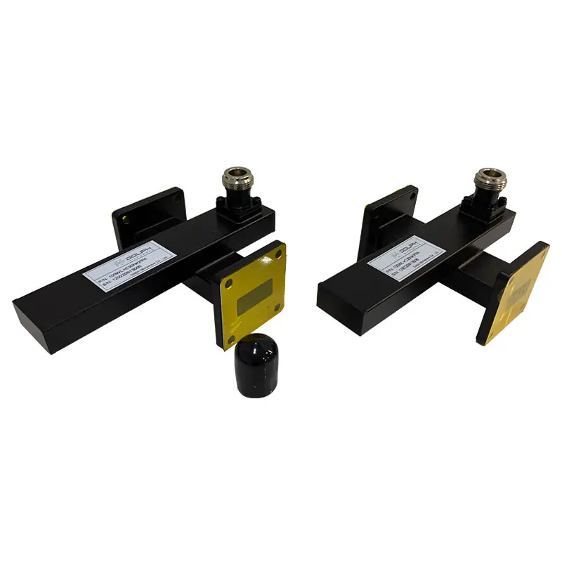
Crossguide Directional Couplers
Crossguide directional couplers are specialized microwave components designed for signal sampling or injection across a broad frequency range. They excel in applications requiring minimal interference with the main signal path, offering precise coupling, high directivity, and low VSWR, making them ideal for power monitoring, signal distribution, and feedback systems.
Compact Waveguide Signal Sampling
Dolph Microwave crossguide directional couplers provide controlled signal sampling or injection in WR430 through WR28 rectangular waveguide systems. Published configurations include four waveguide ports, three waveguide ports, and two waveguide ports with one coaxial sampling port.
Standard nominal coupling values are 20, 30, 40, 50 and 60 dB. The published model tables cover an 18–60 dB coupling range, 18 dB minimum directivity, 10–20% typical operating bandwidth, aluminum or copper construction and multiple IEC/EIA flange arrangements. Non-standard port layouts and coupling requirements are available subject to engineering review.
WR430–WR28
20 / 30 / 40 / 50 / 60 dB
18 dB Min. Directivity
3 Port Styles
Crossguide Coupler Overview
Compact directional sampling where installation space matters
A crossguide directional coupler places a secondary coupling structure across the main rectangular waveguide. A controlled portion of travelling RF energy is directed to a secondary waveguide or coaxial port for monitoring, measurement, feedback or signal injection while the principal signal continues through the main line.
The published specification is intended for applications where compactness is important and 18 dB minimum directivity is suitable for the measurement task. For other coupling structures, review the complete waveguide coupler range.
Main LineInput → Through
→
INPUT
THROUGH
COUPLED PORT
10–20%Typical operating bandwidth
±0.7 dBNominal coupling accuracy
Published Electrical Range
Performance values for initial selection
Standard nominal values are 20, 30, 40, 50 and 60 dB.
Separates the desired travelling-wave sample from the opposite direction.
Most listed models are 1.10; WR28 models are listed at 1.15.
Published for the specified operating bandwidth.
Operating bandwidth is not the complete waveguide band
The specification lists a typical operating bandwidth of 10–20%, with up to 20% of the applicable waveguide bandwidth. Include exact start and stop frequencies in the request.
Power and environmental ratings require confirmation
The standard sheet does not publish CW power, peak power, duty cycle, pressure sealing, temperature range or environmental qualification. Provide these conditions for engineering review and written confirmation.
Dimensions depend on selected interfaces
Overall length and port orientation vary with waveguide size, flange selection and coupled-port style. Use the approved drawing for mechanical integration.
Port Configuration Styles
View flange designation guide ↗
Select the coupling interface that fits the assembly
Four Waveguide Ports
A four-port all-waveguide arrangement with two main-line ports and two secondary-line waveguide ports. The specification uses the DH-xxW+C… model family.
Main VSWR 1.10–1.15Secondary VSWR 1.15
Three Waveguide Ports
An all-waveguide arrangement with two main-line ports and one secondary waveguide port. The specification uses the DH-xxWL+C… model family.
Main VSWR 1.10–1.15Secondary VSWR 1.15
Two Waveguide Ports + One Coax Port
Two main-line waveguide ports with a compact coaxial sampling output. Published table options use Type-N in lower bands and SMA in higher bands; other connector codes remain subject to frequency and layout review.
Main VSWR 1.10–1.15Secondary VSWR 1.25–1.50
Complete Specification Tables
Model coverage by port configuration
Each table retains frequency, bandwidth, VSWR, coupling, directivity, waveguide, flange, connector and material details. Scroll horizontally on smaller screens.
Style 1 — Four Waveguide Ports DH-xxW+C… | Main-line and secondary-line waveguide ports ⌄
| Model No. | Freq. Range (GHz) | Operating BW (%) | Main VSWR Max. | Secondary VSWR Max. | Coupling (dB) | Directivity Min. (dB) | IEC WG | EIA WG | Flange | Material |
|---|---|---|---|---|---|---|---|---|---|---|
| DH-22W+C… | 1.72–2.61 | 10–20 | 1.10 | 1.15 | 18–60 | 18 | R22 | WR430 | FDP / FDM | Al / Cu |
| DH-26W+C… | 2.17–3.30 | 10–20 | 1.10 | 1.15 | 18–60 | 18 | R26 | WR340 | FDP / FDM | Al / Cu |
| DH-32W+C… | 2.60–3.95 | 10–20 | 1.10 | 1.15 | 18–60 | 18 | R32 | WR284 | FDP / FDM | Al / Cu |
| DH-40W+C… | 3.22–4.90 | 10–20 | 1.10 | 1.15 | 18–60 | 18 | R40 | WR229 | FDP / FDM | Al / Cu |
| DH-48W+C… | 3.94–5.99 | 10–20 | 1.10 | 1.15 | 18–60 | 18 | R48 | WR187 | FDP / FDM | Al / Cu |
| DH-58W+C… | 4.64–7.05 | 10–20 | 1.10 | 1.15 | 18–60 | 18 | R58 | WR159 | FDP / FDM | Al / Cu |
| DH-70W+C… | 5.38–8.17 | 10–20 | 1.10 | 1.15 | 18–60 | 18 | R70 | WR137 | FDP / FDM | Al / Cu |
| DH-84W+C… | 6.57–9.99 | 10–20 | 1.10 | 1.15 | 18–60 | 18 | R84 | WR112 | FBP / FBM / FBE | Al / Cu |
| DH-100W+C… | 8.20–12.40 | 10–20 | 1.10 | 1.15 | 18–60 | 18 | R100 | WR90 | FBP / FBM / FBE | Al / Cu |
| DH-120W+C… | 9.84–15.0 | 10–20 | 1.10 | 1.15 | 18–60 | 18 | R120 | WR75 | FBP / FBM / FBE | Al / Cu |
| DH-140W+C… | 11.9–18.0 | 10–20 | 1.10 | 1.15 | 18–60 | 18 | R140 | WR62 | FBP / FBM / FBE | Al / Cu |
| DH-180W+C… | 14.5–22.0 | 10–20 | 1.10 | 1.15 | 18–60 | 18 | R180 | WR51 | FBP / FBM / FBE | Al / Cu |
| DH-220W+C… | 17.6–26.7 | 10–20 | 1.10 | 1.15 | 18–60 | 18 | R220 | WR42 | FBP / FBM / FBE | Al / Cu |
| DH-260W+C… | 21.7–33.0 | 10–20 | 1.10 | 1.15 | 18–60 | 18 | R260 | WR34 | FBP / FBM / FBE | Al / Cu |
| DH-320W+C… | 26.3–40.0 | 10–20 | 1.15 | 1.15 | 18–60 | 18 | R320 | WR28 | FBP / FBM / FBE | Al / Cu |
Style 2 — Three Waveguide Ports DH-xxWL+C… | Two main-line ports and one waveguide coupling port ⌄
| Model No. | Freq. Range (GHz) | Operating BW (%) | Main VSWR Max. | Secondary VSWR Max. | Coupling (dB) | Directivity Min. (dB) | IEC WG | EIA WG | Flange | Material |
|---|---|---|---|---|---|---|---|---|---|---|
| DH-22WL+C… | 1.72–2.61 | 10–20 | 1.10 | 1.15 | 18–60 | 18 | R22 | WR430 | FDP / FDM | Al / Cu |
| DH-26WL+C… | 2.17–3.30 | 10–20 | 1.10 | 1.15 | 18–60 | 18 | R26 | WR340 | FDP / FDM | Al / Cu |
| DH-32WL+C… | 2.60–3.95 | 10–20 | 1.10 | 1.15 | 18–60 | 18 | R32 | WR284 | FDP / FDM | Al / Cu |
| DH-40WL+C… | 3.22–4.90 | 10–20 | 1.10 | 1.15 | 18–60 | 18 | R40 | WR229 | FDP / FDM | Al / Cu |
| DH-48WL+C… | 3.94–5.99 | 10–20 | 1.10 | 1.15 | 18–60 | 18 | R48 | WR187 | FDP / FDM | Al / Cu |
| DH-58WL+C… | 4.64–7.05 | 10–20 | 1.10 | 1.15 | 18–60 | 18 | R58 | WR159 | FDP / FDM | Al / Cu |
| DH-70WL+C… | 5.38–8.17 | 10–20 | 1.10 | 1.15 | 18–60 | 18 | R70 | WR137 | FDP / FDM | Al / Cu |
| DH-84WL+C… | 6.57–9.99 | 10–20 | 1.10 | 1.15 | 18–60 | 18 | R84 | WR112 | FBP / FBM / FBE | Al / Cu |
| DH-100WL+C… | 8.20–12.40 | 10–20 | 1.10 | 1.15 | 18–60 | 18 | R100 | WR90 | FBP / FBM / FBE | Al / Cu |
| DH-120WL+C… | 9.84–15.0 | 10–20 | 1.10 | 1.15 | 18–60 | 18 | R120 | WR75 | FBP / FBM / FBE | Al / Cu |
| DH-140WL+C… | 11.9–18.0 | 10–20 | 1.10 | 1.15 | 18–60 | 18 | R140 | WR62 | FBP / FBM / FBE | Al / Cu |
| DH-180WL+C… | 14.5–22.0 | 10–20 | 1.10 | 1.15 | 18–60 | 18 | R180 | WR51 | FBP / FBM / FBE | Al / Cu |
| DH-220WL+C… | 17.6–26.7 | 10–20 | 1.10 | 1.15 | 18–60 | 18 | R220 | WR42 | FBP / FBM / FBE | Al / Cu |
| DH-260WL+C… | 21.7–33.0 | 10–20 | 1.10 | 1.15 | 18–60 | 18 | R260 | WR34 | FBP / FBM / FBE | Al / Cu |
| DH-320WL+C… | 26.3–40.0 | 10–20 | 1.15 | 1.15 | 18–60 | 18 | R320 | WR28 | FBP / FBM / FBE | Al / Cu |
Style 3 — Two Waveguide Ports + One Coax Port DH-xxWL+C… | Compact coaxial sampled output ⌄
| Model No. | Freq. Range (GHz) | Operating BW (%) | Main VSWR Max. | Secondary VSWR Max. | Coupling (dB) | Directivity Min. (dB) | IEC WG | EIA WG | Flange | Coupled Connector | Material |
|---|---|---|---|---|---|---|---|---|---|---|---|
| DH-22WL+C… | 1.72–2.61 | 10–20 | 1.10 | 1.25–1.50 | 18–60 | 18 | R22 | WR430 | FDP / FDM | Type-N | Al / Cu |
| DH-26WL+C… | 2.17–3.30 | 10–20 | 1.10 | 1.25–1.50 | 18–60 | 18 | R26 | WR340 | FDP / FDM | Type-N | Al / Cu |
| DH-32WL+C… | 2.60–3.95 | 10–20 | 1.10 | 1.25–1.50 | 18–60 | 18 | R32 | WR284 | FDP / FDM | Type-N | Al / Cu |
| DH-40WL+C… | 3.22–4.90 | 10–20 | 1.10 | 1.25–1.50 | 18–60 | 18 | R40 | WR229 | FDP / FDM | Type-N | Al / Cu |
| DH-48WL+C… | 3.94–5.99 | 10–20 | 1.10 | 1.25–1.50 | 18–60 | 18 | R48 | WR187 | FDP / FDM | Type-N | Al / Cu |
| DH-58WL+C… | 4.64–7.05 | 10–20 | 1.10 | 1.25–1.50 | 18–60 | 18 | R58 | WR159 | FDP / FDM | Type-N | Al / Cu |
| DH-70WL+C… | 5.38–8.17 | 10–20 | 1.10 | 1.25–1.50 | 18–60 | 18 | R70 | WR137 | FDP / FDM | Type-N | Al / Cu |
| DH-84WL+C… | 6.57–9.99 | 10–20 | 1.10 | 1.25–1.50 | 18–60 | 18 | R84 | WR112 | FBP / FBM / FBE | SMA | Al / Cu |
| DH-100WL+C… | 8.20–12.40 | 10–20 | 1.10 | 1.25–1.50 | 18–60 | 18 | R100 | WR90 | FBP / FBM / FBE | SMA | Al / Cu |
| DH-120WL+C… | 9.84–15.0 | 10–20 | 1.10 | 1.25–1.50 | 18–60 | 18 | R120 | WR75 | FBP / FBM / FBE | SMA | Al / Cu |
| DH-140WL+C… | 11.9–18.0 | 10–20 | 1.10 | 1.25–1.50 | 18–60 | 18 | R140 | WR62 | FBP / FBM / FBE | SMA | Al / Cu |
| DH-180WL+C… | 14.5–22.0 | 10–20 | 1.10 | 1.25–1.50 | 18–60 | 18 | R180 | WR51 | FBP / FBM / FBE | SMA | Al / Cu |
| DH-220WL+C… | 17.6–26.7 | 10–20 | 1.10 | 1.25–1.50 | 18–60 | 18 | R220 | WR42 | FBP / FBM / FBE | SMA | Al / Cu |
| DH-260WL+C… | 21.7–33.0 | 10–20 | 1.10 | 1.25–1.50 | 18–60 | 18 | R260 | WR34 | FBP / FBM / FBE | SMA | Al / Cu |
| DH-320WL+C… | 26.3–40.0 | 10–20 | 1.15 | 1.25–1.50 | 18–60 | 18 | R320 | WR28 | FBP / FBM / FBE | SMA | Al / Cu |
Ordering Code
Build the required part number
Example
DH100WL+C30NKPMA
The complete code identifies waveguide size, directional configuration, coupling value, connector, connector interface, flange arrangement and material.
100Waveguide size code | WR90
WL+CUni-directional crossguide coupler
WL+2CBi-directional crossguide coupler
30Forward or reverse coupling | 30 dB
NType-N coupled connector
KFemale connector interface
PRectangular flat flange
MRectangular grooved flange
A / CAluminum / Copper material
Manufacturing and Documentation
Confirm the build against the approved configuration
Material
Published options are aluminum and copper. The exact material should be confirmed in the part number, quotation and drawing.
Finish
The specification lists corrosion protection with a black top coat. Other finishes or paint colors may be reviewed upon request.
Mechanical approval
Overall dimensions and port orientation vary by waveguide, flange and coupled-port configuration. Use the approved drawing for integration.
Application review
Provide power, duty cycle, mismatch, environmental conditions, labeling and documentation requirements before final confirmation.
Related Products and Engineering Resources
Continue product comparison and technical selection
Frequently Asked Questions
Crossguide coupler selection questions
What frequency and waveguide sizes are covered?⌄
The current specification covers 1.72–40 GHz across IEC R22–R320 and EIA WR430–WR28. The exact operating window for a selected coupler is typically 10–20% of the applicable waveguide bandwidth.
Which coupling values are standard?⌄
Standard nominal values are 20, 30, 40, 50 and 60 dB. The model tables state an 18–60 dB coupling range, nominal accuracy of ±0.7 dB and frequency sensitivity of ±1 dB.
Can the coupled output be waveguide or coaxial?⌄
Yes. Published styles include all-waveguide arrangements with three or four waveguide ports and a two-waveguide-port configuration with one coaxial coupled output.
Are all connector families available at every frequency?⌄
No. Connector availability depends on frequency, coupling level and mechanical layout. The standard coaxial-output table uses Type-N in lower bands and SMA in higher bands.
Is power handling included in the standard table?⌄
No published CW or peak power rating is shown. Include power, duty cycle, load mismatch and environmental conditions in the request for review.
Can a non-standard port layout be reviewed?⌄
Yes. Special multi-port crossguide couplers can be reviewed for project-specific requirements. Provide a drawing, interface list or dimensional envelope.
What finish is supplied?⌄
The specification lists corrosion protection plus a black top coat. Other finishes or paint colors may be reviewed upon request.
What should be approved before production?⌄
Confirm operating band, coupling and direction, port configuration, flange and connector designations, material, finish, power conditions, mechanical envelope, labeling and documentation in the quotation and approved drawing.
Engineering Review
Send the frequency band, coupling and port drawing
Dolph Microwave can review a standard model or project-specific crossguide layout and confirm the electrical, mechanical and finish details in the quotation and drawing.







