

Dolph Microwave
Low-Power Short Waveguide Terminations
Use a short waveguide termination when you need to end the RF path in a compact space. Select the load by frequency, flange and CW power before checking the overall length.
- Combined model coverage
- 1.13–40 GHz
- Listed VSWR
- 1.2:1
- Model lengths
- 20–160 mm
Before you order
Start with power, then check the space
CW power comes first
The WR650 row lists 2–50 W, while the WR28 row lists 2–15 W. These are low-power loads; choose the exact rating to match the applied signal.
Overall length changes by band
The listed WR650 load is 160 mm long. The WR28 version is 20 mm long. The table retains the dimensions for every model between them.
Flange and finish
The table lists Al/Cu bodies with Chromate/Painted finish and IP65. Confirm the required cover or grooved flange and contact finish with the part number.
For a measurement setup, you may also need a waveguide fixed attenuator or a waveguide calibration kit.
For the rest of your setup
Testing at more power?
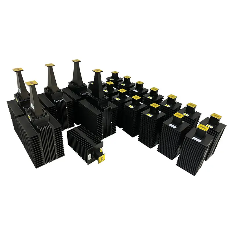
A small termination is not a substitute for a higher-power load. If your test level exceeds the selected CW rating, compare the high-power termination range before placing the order.
View high-power waveguide terminationsTechnical data
Specifications & dimensions
Swipe or scroll across the table to see all columns.
| MODEL | FREQUENCY RANGE(GHz) | WG SIZE | VSWR | POWER RATING CW (W) | FLANGES TYPE | LENGTH (mm) | INGRESS PROTECTION | MATERIAL | FINISH | DATASHEET | ||
|---|---|---|---|---|---|---|---|---|---|---|---|---|
| COVER | GROOVED | |||||||||||
| DH-14WMPL… | 1.13-1.73 | WR650 | 1.2:1 | 2~50 | UDR14 | PDR14 | 160 | IP65 | Al/Cu | Chromate/Painted | STEP | |
| DH-18WMPL… | 1.45-2.2 | WR510 | 1.2:1 | 2~50 | UDR18 | PDR18 | 160 | IP65 | Al/Cu | Chromate/Painted | STEP | |
| DH-22WMPL… | 1.72-2.61 | WR430 | 1.2:1 | 2~50 | UDR22 | PDR22 | 145 | IP65 | Al/Cu | Chromate/Painted | STEP | |
| DH-26WMPL… | 2.17-3.3 | WR340 | 1.2:1 | 2~50 | UDR26 | PDR26 | 120 | IP65 | Al/Cu | Chromate/Painted | STEP | |
| DH-32WMPL… | 2.6-3.95 | WR284 | 1.2:1 | 2~50 | UDR32 | PDR32 | 100 | IP65 | Al/Cu | Chromate/Painted | STEP | |
| DH-40WMPL… | 3.22-4.9 | WR229 | 1.2:1 | 2~50 | UDR40 | PDR40 | 80 | IP65 | Al/Cu | Chromate/Painted | STEP | |
| DH-48WMPL… | 3.94-5.99 | WR187 | 1.2:1 | 2~50 | UDR48 | PDR48 | 55 | IP65 | Al/Cu | Chromate/Painted | STEP | |
| DH-58WMPL… | 4.64-7.05 | WR159 | 1.2:1 | 2~50 | UDR58 | PDR58 | 50 | IP65 | Al/Cu | Chromate/Painted | STEP | |
| DH-70WMPL… | 5.38-8.17 | WR137 | 1.2:1 | 2~30 | UDR70 | PDR70 | 45 | IP65 | Al/Cu | Chromate/Painted | STEP | |
| DH-84WMPL… | 6.57-9.99 | WR112 | 1.2:1 | 2~30 | UDR84/UBR84 | PDR84/PBR84 | 40 | IP65 | Al/Cu | Chromate/Painted | STEP | |
| DH-100WMPL… | 8.2-12.5 | WR90 | 1.2:1 | 2~20 | UDR100/UBR100 | PDR100/PBR100 | 40 | IP65 | Al/Cu | Chromate/Painted | STEP | |
| DH-120WMPL… | 9.84-15 | WR75 | 1.2:1 | 2~20 | UBR120 | PBR120 | 35 | IP65 | Al/Cu | Chromate/Painted | STEP | |
| DH-140WMPL… | 11.9-18 | WR62 | 1.2:1 | 2~20 | UBR140 | PBR140 | 30 | IP65 | Al/Cu | Chromate/Painted | STEP | |
| DH-180WMPL… | 14.5-22 | WR51 | 1.2:1 | 2~20 | UBR180 | PBR180 | 30 | IP65 | Al/Cu | Chromate/Painted | STEP | |
| DH-220WMPL… | 17.6-26.7 | WR42 | 1.2:1 | 2~15 | UBR220 | PBR220 | 30 | IP65 | Al/Cu | Chromate/Painted | STEP | |
| DH-260WMPL… | 21.7-33 | WR34 | 1.2:1 | 2~15 | UBR260 | PBR260 | 20 | IP65 | Al/Cu | Chromate/Painted | STEP | |
| DH-320WMPL… | 26.3-40 | WR28 | 1.2:1 | 2~15 | UBR320 | PBR320 | 20 | IP65 | Al/Cu | Chromate/Painted | STEP | |
| Part Number Guide: DH-100WMPL20PA “100”—Waveguide Size | WR90 “WMPL”—Waveguide Type | Precision Low Power Min. (Short) Loads “20”— Power Rating | 20 W “P”— Flange Type | Rectangular Flat “M”— Flange Type | Rectangular Grooved “A/C”— Material | Aluminium, Cu | ||||||||||||
| Note: All Dolph-MW models include an surtec/corrosion protection treatment and are painted flat black. Flanges are unplated, polished and surtec. Other finishes and paint colors are available upon request. | ||||||||||||
Materials & ordering options
Technical documents
Questions before ordering
Can this load be connected directly to a high-power amplifier?
Only if the power reaching the load is within its selected rating. The product table specifies low-power CW ranges, not unrestricted amplifier output.
What does “short” refer to?
It refers to the compact physical format of this matched load. It is not a waveguide shorting plate.
Related products

Standard Waveguide_Precision Waveguide Calibration Kits
View productFor calibration before waveguide measurements.
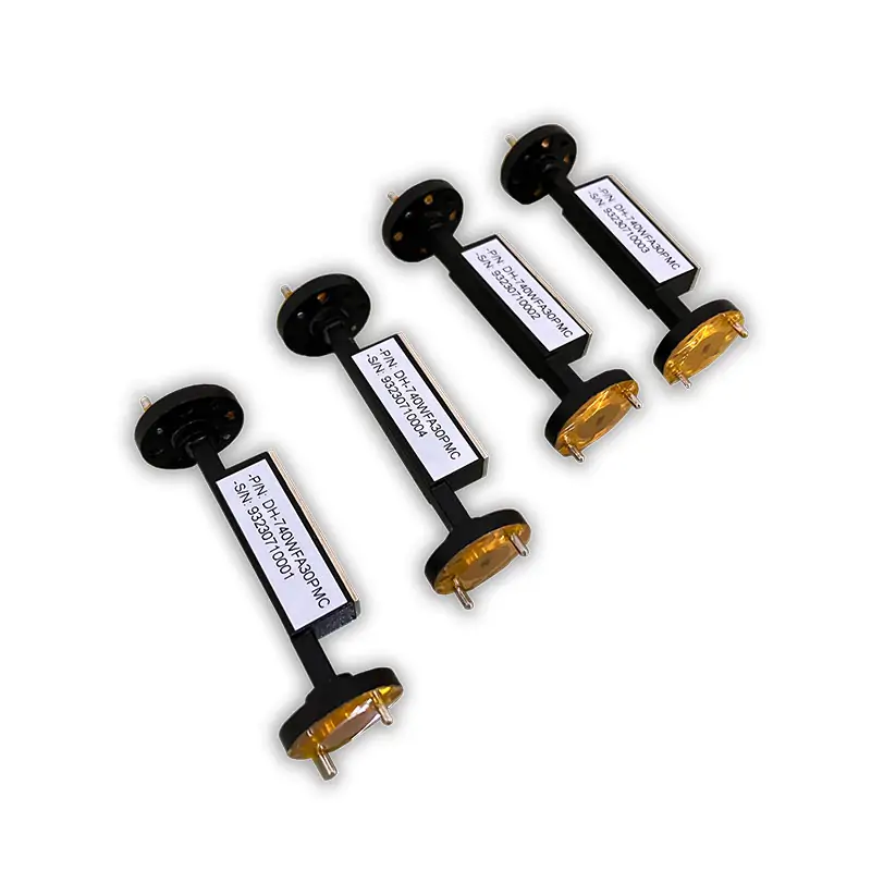
Waveguide Fixed Attenuator
View productFor a specified attenuation step in the test path.

Standard Waveguide_High-Power Waveguide Coaxial Adapter
View productFor connecting the waveguide path to a coaxial interface.
Tell us what you need
Have a model or drawing?
Send operating frequency, WR size, power at the load, required flange, available length and quantity. Include duty cycle for pulsed tests.






