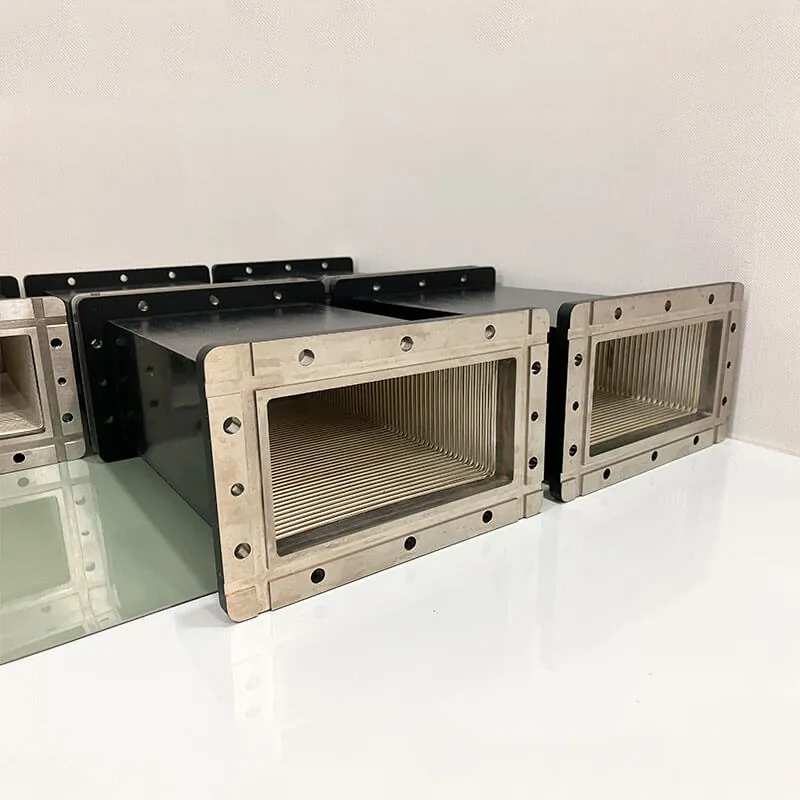
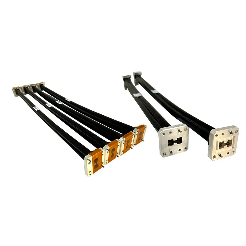
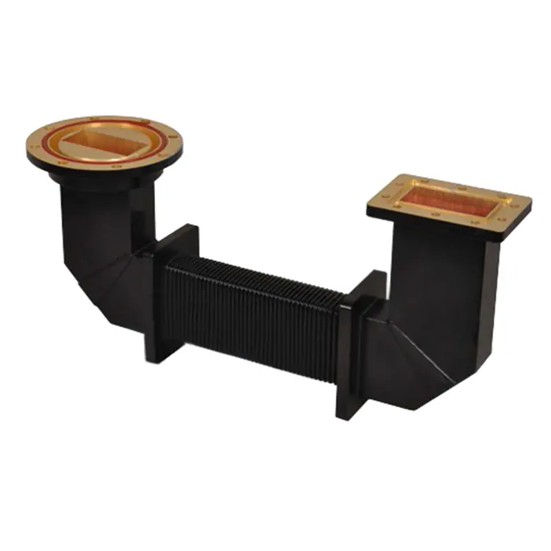
High Power WR650 Flexible Waveguide

Discover Dolph-MW’s extensive collection of high-power, low-frequency WR650 flexible waveguide products and accessories, compliant with IEC Standard R14. The WR650, a rectangular waveguide measuring 6. 5 inches wide and 3. 25 inches high, operates between 1. 12 and 1. 70 GHz. Ideal for high-power applications, it efficiently transmits RF signals with an impressive insertion loss of less than 0. 01 dB/m.

Model  DH-14WWEL300PMC

DH-14WWEL300PMC at a Glance

This published WR650 build covers 1.12-1.7 GHz in a 300 mm non-twistable section. It is specified with a WR650g grooved brass flange, nickel-plated flange face, silicone rubber / polysulfide sealant jacket and 3 PSIG maximum pressure.
1.12-1.7 GHz
Frequency range
6.0 MW
Peak power
≤1.1:1
VSWR
0.035 dB
Insertion loss
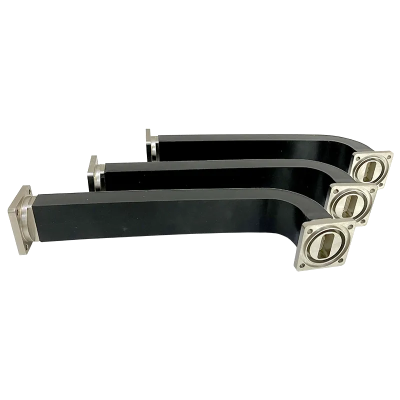
Dolph Microwave DH-14WWEL300PMC high-power WR650 flexible waveguide

Complete Product Specification

Use these values to screen the exact DH-14WWEL300PMC model. If your required length, pressure, flange or environment differs, send the requirement before ordering.

Check Your Configuration
ModelDH-14WWEL300PMC
Frequency Range1.12-1.7 GHz
VSWR≤1.1:1
Insertion Loss0.035 dB
Peak Power6.0 MW
Waveguide TypeWR650
JacketSilicone Rubber / Polysulfide Sealant
Conductor MaterialBrass, Non-Twistable
Flex Material FinishSilver Plate
ConstructionSilver Brazed
Inside Diameter Size165.10 mm*82.55 mm
Flange TypeWR650g (Grooved), Brass Per Mil-417 B/U
Flange Face FinishNickel Plate
Length (L)300 mm
Max. Pressure3 PSIG
Operation Temp.-30℃~ +75℃
Storage Temp.-55℃~ +85℃
Dolph Microwave flexible waveguide product range

Send These Details with the RFQ

A drawing or clear interface data lets our engineering team check the published model against your installation before quotation.

RF conditionsOperating frequency plus average and peak transmitter power when available.
Mating interfaceFlange designation, mating face, gasket requirement and any existing part number.
Mechanical fitOverall length, installation envelope, support points and required flange orientation.
Pressure and environmentRequired line pressure, operating temperature and any inspection or RF records needed with delivery.

Built and Checked in Xi’an

Dolph Microwave has manufactured microwave components since 2001. In-house capabilities include CNC machining, waveguide forming and bending, brazing, plating, assembly and dimensional inspection. RF vector and scalar measurement capability is listed up to 100 GHz.

Since 2001Microwave manufacturing
ISO 9001:2015Quality certification
Up to 100 GHzListed RF measurement
1-Year WarrantySubject to warranty terms

If the 300 mm Standard Build Does Not Fit

For a different length, routed geometry or end interface, send the installation drawing for a custom waveguide assembly review.

If you need another flexible waveguide size or construction, review the Seamless Flexible WG range. For a waveguide-to-coaxial interface, use the High-Power Waveguide Coaxial Adapter product family instead.

For complete routing work that combines straight sections, bends, transitions and flexible sections, see Dolph’s waveguide components and assembly capabilities.

Review a Custom Assembly
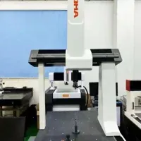
CNC machining at Dolph Microwave Coordinate measuring machine used for dimensional inspection at Dolph Microwave

Verification Before Delivery

The DH-14WWEL300PMC product PDF includes the model specification, outline drawing and typical RF performance plots. If your project requires specific inspection or RF records, list them in the RFQ so they can be reviewed before quotation.

Dolph’s manufacturing capability covers forming, brazing, plating, assembly and dimensional inspection in-house. The company also lists a one-year warranty against defective material and workmanship, subject to its warranty terms.

Technical Downloads

Download the exact DH-14WWEL300PMC datasheet for the specification, outline drawing and typical performance plots. Use the separate flange file when checking interface designations.


Scroll to Top
Blank Form (#3)