
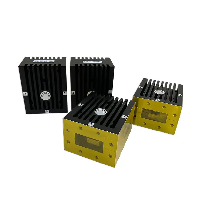
Dolph Microwave / Waveguide circulators
A circulator that fits your band, power and waveguide.
Start with your operating frequencies, then check the actual model’s loss, isolation, VSWR and port dimensions. The published tables cover general and small-type circulators; we can review a different electrical or mechanical configuration when a catalog part does not fit.
Compare published modelsFind a starting point
Already know your operating band?
These are real entries from the manufacturer’s general circulator sheet. Use them to find the relevant part of the full table, then check all its specifications together.
A wide family range does not mean one circulator operates from 0.9 to 112 GHz. If your exact band falls between the listed models, send your required lower and upper frequencies for a custom-model review.
What to send for a quoteProduct options
What you can specify
The product page also lists standard catalog models and customization to electrical and mechanical specifications. Please confirm values against the selected model and the latest drawing before placing an order.
Mechanical fit
The flange matters as much as the frequency.
Check your waveguide size, flange designation, mounting space and port direction before ordering. UG and CPR are flange families, not a complete drawing or a guarantee of interchangeability.
Waveguide flange size guideSignal routing
Confirm which port sends power where.
A three-port circulator directs energy between ports in sequence. Give the team your required input, output and third-port connections so the port orientation can be checked against the drawing.
- Match the full operating frequency range.
- Check forward loss, reverse loss and VSWR on the same model row.
- State the power and reflection conditions at the ports.
Concept diagram, not a model-specific port drawing. Confirm routing and mounting orientation with engineering.
Original manufacturer data
General circulator model specifications
All published general-model rows are shown below. Read across the whole row: frequency, WG type, forward and reverse loss, VSWR, reference power and size are tied to that model.
| Model No | Freq Range (GHz) | WG Type | Forward Loss (dB) | Reverse Loss (dB) | VSWR | Ref. Power | Size |
|---|---|---|---|---|---|---|---|
| DH-HBG9069 | 0.9-0.93 | BJ9 | 0.30 | 20 | 1.2 | 75KW | 665*550*215 |
| DH-HBG9068 | 1.13-1.73 | BJ14 | 0.30 | 20 | 1.25 | 250W | 360*360*138.1 |
| DH-HBG9048 | 2.015-2.13 | BJ22 | 0.20 | 25 | 1.12 | 20KW | 300*260*114.6 |
| DH-HBG9075 | 4.3-5.1 | BJ48 | 0.20 | 20 | 1.20 | 500W | 114*114*63.5 |
| DH-HBG9040 | 5.25-5.75 | BJ58 | 0.30 | 20 | 1.2 | 3KW | 81*62*90 |
| DH-HBG9078 | 7.7-7.8 | BJ70 | 0.25 | 20 | 1.2 | 600W | 60*60*47.8 |
| DH-HBZ9003 | 8.6-9.6 | BJ100 | 0.25 | 20 | 1.25 | 300W | 50.8*50.8*41.4 |
| DH-HBG9067 | 9-9.5 | BJ100 | 0.30 | 20 | 1.2 | 250W | 41.4*41.4*50 |
| DH-HBG9066 | 9-10.2 | BJ100 | 0.20 | 20 | 1.2 | 900W | 80*80*60 |
| DH-HBP9014 | 15-18 | BJ180 | 0.30 | 18 | 1.2 | 150W | 38*48*30.2 |
| DH-HBP9033 | 19-22.9 | BJ180 | 0.30 | 20 | 1.2 | 100W | 35*24*16 |
| DH-HBG9069 | 25.5-26 | BJ320 | 0.20 | 25 | 1.15 | 40W | 23*26.9*19.0 |
| DH-HBG9063 | 29.5-30 | BJ320 | 0.20 | 25 | 1.13 | 40W | 25*47*19.1 |
| DH-HBG9053 | 30-36 | BJ320 | 0.25 | 23 | 1.2 | 100W | 31*25*19 |
| DH-HBP9038 | 34-36 | BJ320 | 0.25 | 20 | 1.2 | 40W | 19*23*19.1 |
| DH-HBH9018A | 56.5-63.5 | BJ620 | 0.70 | 17 | 1.35 | 2W | 43*39.5*12.5 |
| DH-HBH9019 | 91.5-93.5 | BJ900 | 0.60 | 18 | 1.35 | 2W | 8.8*12*22 |
| DH-HBH9020 | 92-96 | BJ900 | 0.60 | 18 | 1.35 | 2W | 20*26*13 |
The source PDF prints “DH-HBG9069” twice with different operating frequencies and dimensions. Both entries are kept as published; please confirm the correct ordering number. “Ref. Power” is the PDF’s original heading, and its “Size” column does not state measurement units.
Original general circulator PDFPublished typical data
Typical values by frequency band
Compare the effect of bandwidth within a listed band. These typical values are not purchase specifications for every model. The PDF notes that a wider operating band can require a longer dimension along the transmission direction.
| Freq Band | Bandwidth | Forward Loss (dB) | Reverse Loss (dB) | VSWR | Ave. Power |
|---|---|---|---|---|---|
| L | 5% | 0.20 | 23 | 1.15 | 2KW |
| L | 10% | 0.25 | 21 | 1.17 | 2KW |
| L | 20% | 0.30 | 20 | 1.20 | 2KW |
| S | 5% | 0.20 | 23 | 1.15 | 1KW |
| S | 10% | 0.25 | 21 | 1.17 | 1KW |
| S | 20% | 0.30 | 20 | 1.20 | 1KW |
| C | 5% | 0.20 | 23 | 1.15 | 500W |
| C | 10% | 0.25 | 21 | 1.17 | 500W |
| C | 20% | 0.30 | 20 | 1.20 | 500W |
| X | 10% | 0.20 | 23 | 1.15 | 300W |
| X | 20% | 0.25 | 20 | 1.20 | 300W |
| Ku | 10% | 0.20 | 23 | 1.15 | 120W |
| Ku | 20% | 0.25 | 20 | 1.20 | 120W |
| K | 10% | 0.20 | 23 | 1.15 | 100W |
| K | 20% | 0.25 | 20 | 1.20 | 100W |
| Ka | 5% | 0.25 | 23 | 1.15 | 50W |
| Ka | 10% | 0.30 | 20 | 1.20 | 50W |
| V | 10% | 0.60 | 17 | 1.35 | 2W |
| U | 5% | 0.60 | 17 | 1.35 | 2W |
| E | 5% | 0.60 | 17 | 1.35 | 2W |
“Ave. Power” is retained exactly as labelled by the manufacturer. The general PDF also contains a dimension illustration marked A, B and C; use the original sheet and request a model-specific outline drawing.
For tighter layouts
Small-type non-standard circulators
The manufacturer lists these configurations for smaller transmission-direction dimensions. The port sizes and overall sizes are preserved as printed; confirm the drawing before using them in a fixed mounting space.
| Model No | Freq Range (GHz) | WG Port Size | Forward Loss (dB) | Reverse Loss (dB) | VSWR | Ref. Power | Size |
|---|---|---|---|---|---|---|---|
| DH-HBG9012 | 13.5-13.9 | 15*3.5 | 0.35 | 20 | 1.3 | 400W/125W | 24*424*16 |
| DH-HBG9022 | 14.5-14.9 | 15*4 | 0.30 | 22 | 1.20 | 2.5KW/10W | 28*28*25 |
| DH-HBP9042 | 15-17 | 13*2 | 0.40 | 20 | 1,20 | 40W | 68*24*16 |
| DH-HBP9026 | 16.25-16.75 | 11.48*3 | 0.30 | 20 | 1.25 | 400W(PK)/125(AVG) | 17(27)*22*15 |
Original transcription retained: the source prints “24*424*16” for DH-HBG9012 and “1,20” for the DH-HBP9042 VSWR. Do not treat either as a corrected value without checking the current specification. The small-type PDF includes an A/B/C dimension drawing.
Original small-type circulator PDFManufacturer-listed applications
Where these circulators are used
Military systems
Radar and communication RF paths. Program-specific qualification needs separate confirmation.
Commercial telecom
Satellite and wireless communication equipment.
Space exploration
Satellite-related projects; the product listing does not establish space-flight qualification.
Scientific research
Physics and aerospace research setups.
Medical imaging
MRI applications are named on the source page; medical-system suitability and approvals must be verified separately.
Read the original documents
Specification sheets and drawings
Model data, typical band values and A/B/C drawing
Compact model table and dimensional illustration
Linked file is an isolator sheet; verify the circulator file
The source product page labels its third download a “Differential Phase Shift Waveguide Circulator Specification Sheet”, but its linked file is titled “High-Power Differential Phase-Shift Waveguide Isolator”. Isolator ratings are not being presented as circulator ratings here. Ask for the correct circulator drawing and current document revision.
Helpful engineering references
Check the details before your RFQ
Other products in the RF path
You may also need
Model check and quotation
Send the details that decide the part.
Have a model number? Include it. Working from a replacement or a new design? Send the operating conditions and a drawing if you have one. We can check the catalog match or review a custom configuration.
Email your requirements ↗Use the enquiry button already provided by this product page if you prefer the site’s standard RFQ process.
- FrequencyLower and upper GHz limits; bandwidth.
- Model / waveguideModel number if known; WR or BJ size.
- Ports and flangeInput/output/third port mapping; exact UG or CPR designation.
- RF requirementsForward loss, reverse loss / isolation and VSWR.
- Power conditionsForward and reflected power; CW or pulsed, peak and duty cycle if applicable.
- Physical fitEnvelope, mounting orientation and any existing drawing.
- EnvironmentOperating temperature and any pressure, cooling or other constraints.
- Purchase detailsQuantity and any required drawing or test documentation.







