
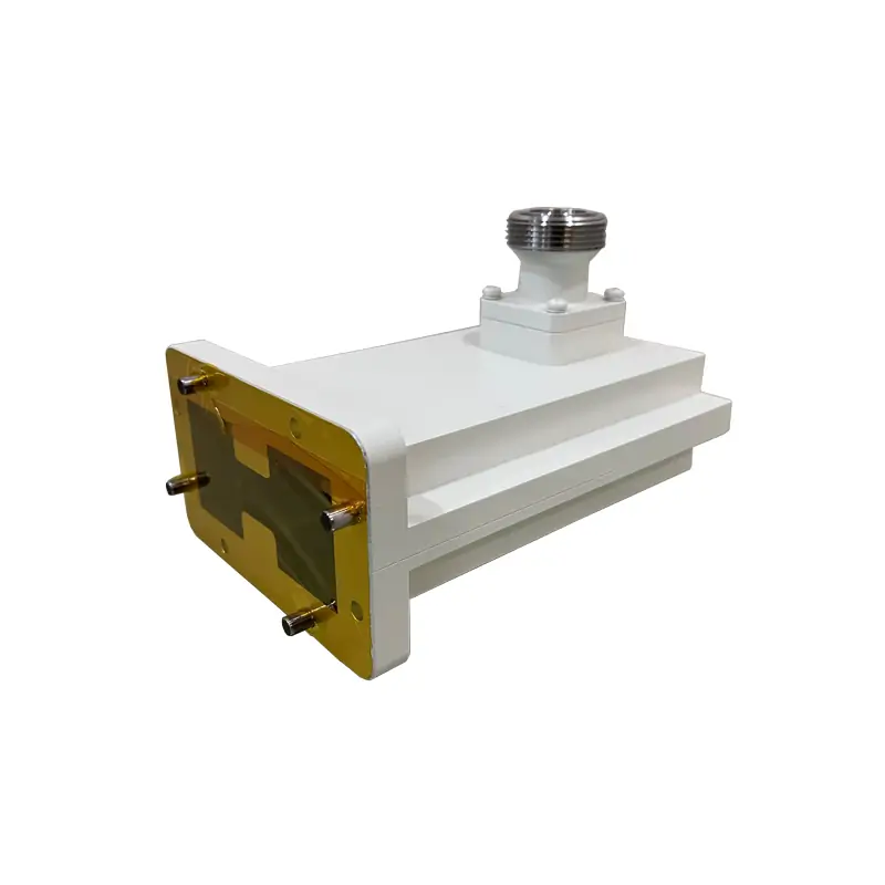
High-Power Double-Ridged Waveguide to Coaxial Adapter
For connecting a high-power double-ridged waveguide line to a coaxial cable or RF module. The listed models cover WRD840 through WRD750, with DIN 7/16 or N-type interfaces and right-angle or end-launch layouts. Average power is model-dependent, up to 1000 W in the published table.
Frequency alone is not enough to pick the adapter.
Use the full operating band
Send the lower and upper frequency limits. A center frequency can point to more than one waveguide family.
Match the exact WRD flange
Confirm the WRD size and whether the mating flange is cover or grooved. Bolt pattern and sealing face matter.
Choose the coax connector
The current high-power rows list DIN 7/16 for WRD840 and N-K for the other listed WRD sizes.
State the real power condition
Give average power. For pulsed systems, also give peak power, pulse width and duty cycle.
If power or flange selection is still open, see the waveguide power handling guide and the waveguide flange size guide.
Right-angle or end-launch: choose the one that fits the real assembly.
Check connector clearance before the model is released.
On a bench, both layouts can look simple. Inside a rack, antenna feed or test fixture, the cable bend and connector access often decide which one works.
- WHPCA: high-power right-angle waveguide to coaxial adapter.
- WHPECA: high-power end-launch waveguide to coaxial adapter.
- Confirm the available envelope, cable direction and flange clocking from your drawing or installation space.
Right-angle layout
Use this when the coax cable needs to leave from the side of the waveguide body or when axial space is tight.
End-launch layout
Use this when an axial connector position suits the assembly. Leave enough room for the mating connector and cable bend.
Use the table row, not the biggest number on the page.
Important: the page overview says 0.84–40 GHz, but the current high-power rows shown below stop at 18.5 GHz. If your requirement is above the listed rows, send the exact band and connector requirement for confirmation instead of assuming that every high-power configuration extends to 40 GHz.
What the published page says about the product family
Up to 1000 W average power, model-dependent.
The current overview states 0.84–40 GHz. The detailed high-power rows currently published below cover 0.84–18.5 GHz.
The current feature copy states ≤1.4:1. Individual rows list 1.25:1, 1.3:1 or 1.4:1.
The current feature copy states ≤0.4 dB. Listed rows show 0.3 or 0.4 dB.
The page lists precision-machined aluminum or aluminum/copper construction with Surtec 650 or chromate corrosion protection.
DIN 7-16, N-type female/male and SMA are mentioned in the current feature copy.
Connector check: the detailed high-power rows currently shown on the page list DIN 7/16 and N-K. SMA is mentioned in the broader feature copy but does not appear in those listed rows, so an SMA high-power request should be confirmed by exact model before ordering.
Where the current product page positions this adapter
Find the WRD family first, then check the full row.
| WG SIZE | FREQUENCY | CONNECTOR | AVG. POWER | COVER FLANGE | GROOVED FLANGE |
|---|---|---|---|---|---|
| WRD840 | 0.84–2.0 GHz | DIN 7/16 | 800 / 1000 W | FPWRD840U24 | FMWRD840U24 |
| WRD150 | 1.5–3.6 GHz | N-K | 600 W | FPWRD150D24 | FMWRD150D24 |
| WRD200 | 2.0–4.8 GHz | N-K | 500 W | FPWRD200D24 | FMWRD200D24 |
| WRD250 | 2.6–7.8 GHz | N-K | 500 W | FPWRD250D30 | FMWRD250D30 |
| WRD350 | 3.5–8.2 GHz | N-K | 500 W | FPWRD350D24 | FMWRD350D24 |
| WRD475 | 4.75–11.0 GHz | N-K | 500 W | FPWRD475D24 | FMWRD475D24 |
| WRD500 | 5.0–18.0 GHz | N-K | 500 W | FPWRD500D36 | FMWRD500D36 |
| WRD580 | 5.8–16.0 GHz | N-K | 500 W | FPWRD580D28 | FMWRD580D28 |
| WRD650 | 6.5–18.0 GHz | N-K | 500 W | FPWRD650D28 | FMWRD650D28 |
| WRD700 | 7.0–18.5 GHz | N-K | 500 W | FPWRD700D26 | FMWRD700D26 |
| WRD750 | 7.5–18.0 GHz | N-K | 500 W | FPWRD750D24 | FMWRD750D24 |
This shortlist is only a faster way to find the relevant WRD family. The complete published table below is kept in full and remains the detailed reference.
All current high-power model rows
| MODEL | FREQ. RANGE (GHz) | WG SIZE | VSWR | IL (dB) | CONNECTOR Type | AVG. POWER (W) | COVER FLANGE | GROOVED FLANGE | MATERIAL | FINISH | DATASHEET |
|---|---|---|---|---|---|---|---|---|---|---|---|
| DH-840DRWHPCA… | 0.84-2.0 | WRD840 | 1.25:1 | 0.3 | DIN 7/16 | 1000 | FPWRD840U24 | FMWRD840U24 | Al | Chromate/Painted | PDFSTEP |
| DH-840DRWHPECA… | 0.84-2.0 | WRD840 | 1.25:1 | 0.3 | DIN 7/16 | 1000 | FPWRD840U24 | FMWRD840U24 | Al | Chromate/Painted | PDFSTEP |
| DH-840DRWHPCA… | 0.84-2.0 | WRD840 | 1.25:1 | 0.3 | DIN 7/16 | 1000 | FPWRD840U24 | FMWRD840U24 | Al | Chromate/Painted | PDFSTEP |
| DH-840DRWHPECA… | 0.84-2.0 | WRD840 | 1.25:1 | 0.3 | DIN 7/16 | 1000 | FPWRD840U24 | FMWRD840U24 | Al | Chromate/Painted | PDFSTEP |
| DH-840DRWHPCA… | 0.84-2.0 | WRD840 | 1.25:1 | 0.3 | DIN 7/16 | 800 | FPWRD840U24 | FMWRD840U24 | Al | Chromate/Painted | PDFSTEP |
| DH-840DRWHPECA… | 0.84-2.0 | WRD840 | 1.25:1 | 0.3 | DIN 7/16 | 800 | FPWRD840U24 | FMWRD840U24 | Al | Chromate/Painted | PDFSTEP |
| DH-150DRWHPCA… | 1.5-3.6 | WRD150 | 1.25:1 | 0.3 | N-K | 600 | FPWRD150D24 | FMWRD150D24 | Al | Chromate/Painted | PDFSTEP |
| DH-150DRWHPECA… | 1.5-3.6 | WRD150 | 1.25:1 | 0.3 | N-K | 600 | FPWRD150D24 | FMWRD150D24 | Al | Chromate/Painted | PDFSTEP |
| DH-200DRWHPCA… | 2.0-4.8 | WRD200 | 1.4:1 | 0.3 | N-K | 500 | FPWRD200D24 | FMWRD200D24 | Al | Chromate/Painted | PDFSTEP |
| DH-200DRWHPECA… | 2.0-4.8 | WRD200 | 1.4:1 | 0.3 | N-K | 500 | FPWRD200D24 | FMWRD200D24 | Al | Chromate/Painted | PDFSTEP |
| DH-250DRWHPCA… | 2.6-7.8 | WRD250 | 1.4:1 | 0.4 | N-K | 500 | FPWRD250D30 | FMWRD250D30 | Al | Chromate/Painted | PDFSTEP |
| DH-250DRWHPECA… | 2.6-7.8 | WRD250 | 1.4:1 | 0.4 | N-K | 500 | FPWRD250D30 | FMWRD250D30 | Al | Chromate/Painted | PDFSTEP |
| DH-350DRWHPCA… | 3.5-8.2 | WRD350 | 1.4:1 | 0.4 | N-K | 500 | FPWRD350D24 | FMWRD350D24 | Al | Chromate/Painted | PDFSTEP |
| DH-350DRWHPECA… | 3.5-8.2 | WRD350 | 1.4:1 | 0.4 | N-K | 500 | FPWRD350D24 | FMWRD350D24 | Al | Chromate/Painted | PDFSTEP |
| DH-475DRWHPCA… | 4.75-11.0 | WRD475 | 1.3:1 | 0.3 | N-K | 500 | FPWRD475D24 | FMWRD475D24 | Al | Chromate/Painted | PDFSTEP |
| DH-475DRWHPECA… | 4.75-11.0 | WRD475 | 1.3:1 | 0.3 | N-K | 500 | FPWRD475D24 | FMWRD475D24 | Al | Chromate/Painted | PDFSTEP |
| DH-500DRWHPCA… | 5.0-18.0 | WRD500 | 1.3:1 | 0.3 | N-K | 500 | FPWRD500D36 | FMWRD500D36 | Al | Chromate/Painted | PDFSTEP |
| DH-500DRWHPECA… | 5.0-18.0 | WRD500 | 1.3:1 | 0.3 | N-K | 500 | FPWRD500D36 | FMWRD500D36 | Al | Chromate/Painted | PDFSTEP |
| DH-580DRWHPCA… | 5.8-16.0 | WRD580 | 1.3:1 | 0.3 | N-K | 500 | FPWRD580D28 | FMWRD580D28 | Al | Chromate/Painted | PDFSTEP |
| DH-580DRWHPECA… | 5.8-16.0 | WRD580 | 1.3:1 | 0.3 | N-K | 500 | FPWRD580D28 | FMWRD580D28 | Al | Chromate/Painted | PDFSTEP |
| DH-650DRWHPCA… | 6.5-18.0 | WRD650 | 1.25:1 | 0.3 | N-K | 500 | FPWRD650D28 | FMWRD650D28 | Al/Cu | Chromate/Painted | PDFSTEP |
| DH-650DRWHPECA… | 6.5-18.0 | WRD650 | 1.25:1 | 0.3 | N-K | 500 | FPWRD650D28 | FMWRD650D28 | Al/Cu | Chromate/Painted | PDFSTEP |
| DH-700DRWHPCA… | 7.0-18.5 | WRD700 | 1.25:1 | 0.3 | N-K | 500 | FPWRD700D26 | FMWRD700D26 | Al/Cu | Chromate/Painted | PDFSTEP |
| DH-700DRWHPECA… | 7.0-18.5 | WRD700 | 1.25:1 | 0.3 | N-K | 500 | FPWRD700D26 | FMWRD700D26 | Al/Cu | Chromate/Painted | PDFSTEP |
| DH-750DRWHPCA… | 7.5-18.0 | WRD750 | 1.3:1 | 0.3 | N-K | 500 | FPWRD750D24 | FMWRD750D24 | Al/Cu | Chromate/Painted | PDFSTEP |
| DH-750DRWHPECA… | 7.5-18.0 | WRD750 | 1.3:1 | 0.3 | N-K | 500 | FPWRD750D24 | FMWRD750D24 | Al/Cu | Chromate/Painted | PDFSTEP |
The repeated WRD840 rows and the separate 1000 W / 800 W entries are retained as they currently appear on the product page. PDF and STEP file labels are also retained in the model matrix.
“Up to 1000 W” does not mean every model is rated for 1000 W.
The current table shows 1000 W and 800 W WRD840 entries, 600 W for WRD150, and 500 W for the listed WRD200 through WRD750 entries. Check power and interface on the same row.
For pulsed systems, the average-power row does not replace peak-power review. Include the pulse conditions in the RFQ.
Bars are a visual comparison of the published average-power values, not a substitute for the selected model datasheet or approved drawing.
Read the code before comparing two quotations.
Finish note retained from the current page
All Dolph-MW models include an surtec/corrosion protection treatment and are painted flat black. Flanges are unplated, polished and surtec. Other finishes and paint colors are available upon request.
A short RFQ can still be complete.
These are the details that usually stop the quote from going back and forth.
Send what is fixed. Mark what can change.
If you already have a drawing, STEP file, old part number or mating-part dimensions, send it. If you do not, the electrical and interface data below is enough to start a model review.
For a mixed waveguide route, the waveguide component sourcing page shows what to include when several parts need to match.
Ask for the evidence your project actually needs.
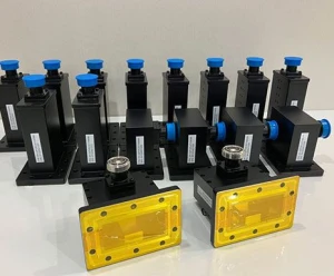
Dolph’s current sourcing page states that machining, forming/bending, brazing, plating, assembly and RF testing are handled in-house. If your order needs a dimensional report, RF data, inspection record, PDF drawing or STEP file, put that requirement in the RFQ so it is part of the quoted scope.
Keep the drawings and flange reference with the RFQ.
Double Ridge Waveguide Components
Broader double-ridged component catalog for interface and family reference.
Download PDFHigh Power Termination
This download remains available exactly as on the current product page.
Download PDFFLANGE TYPE DESIGNATIONS INFORMATION
Reference for Dolph flange codes and standard waveguide flange designations.
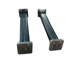
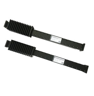
Download PDFParts buyers often review with this adapter
Check the points that can change the final model.
Clear up the interface before the purchase order.
Can I select the model by frequency only?
No. Use the full operating band together with WRD size, flange, connector and launch direction. Two parts can overlap in frequency and still be mechanically incompatible.
Does every model handle 1000 W average power?
No. The current table shows 1000 W and 800 W WRD840 entries, 600 W for WRD150, and 500 W for the listed WRD200 through WRD750 models. Use the power value on the same row as the selected model.
What is the difference between WHPCA and WHPECA?
WHPCA is the published code for the high-power right-angle waveguide-to-coaxial adapter. WHPECA is the end-launch version. Choose according to connector direction and the space available in your assembly.
What if my requirement is above 18.5 GHz?
The current high-power model rows on this page stop at 18.5 GHz, while the overview text references a broader 0.84–40 GHz family range. Send the exact band, WRD interface, connector and power requirement for confirmation. If your power requirement is lower, the standard double-ridged waveguide-to-coax adapter family also includes higher-frequency WRD models.
What should I send if I need a drop-in replacement?
Send the old part number, photos, drawing or measured interface dimensions, the two mating interfaces and any dimensions that cannot change. Add quantity and required PDF, STEP, inspection or RF records.







