Author name: Dolph

How was complete coverage achieved with a minimum s-band antenna gain of -7 dBi

How was complete coverage achieved with a minimum s-band antenna gain of -7 dBi

To achieve complete coverage with a minimum s-band antenna gain of -7 dBi, a straightforward configuration utilizing dual circularly polarized microstrip patch antennas was employed. The configuration involved the implementation of a wide bandwidth, dual circularly polarized truncated corner microstrip antenna, which was complemented by two parasitic patches. To enhance the cross polarization bandwidth, diagonally embedded holes […]

How was complete coverage achieved with a minimum s-band antenna gain of -7 dBi Read More »
[Dolph Microwave] 4.5 Meter Turning Head Antenna with Ext.Ka-band Tx27.5 to 31.0 GHz, Rx17.7-21.2GHz

[Dolph Microwave] 4.5 Meter Turning Head Antenna with Ext.Ka-band Tx27.5 to 31.0 GHz, Rx17.7-21.2GHz

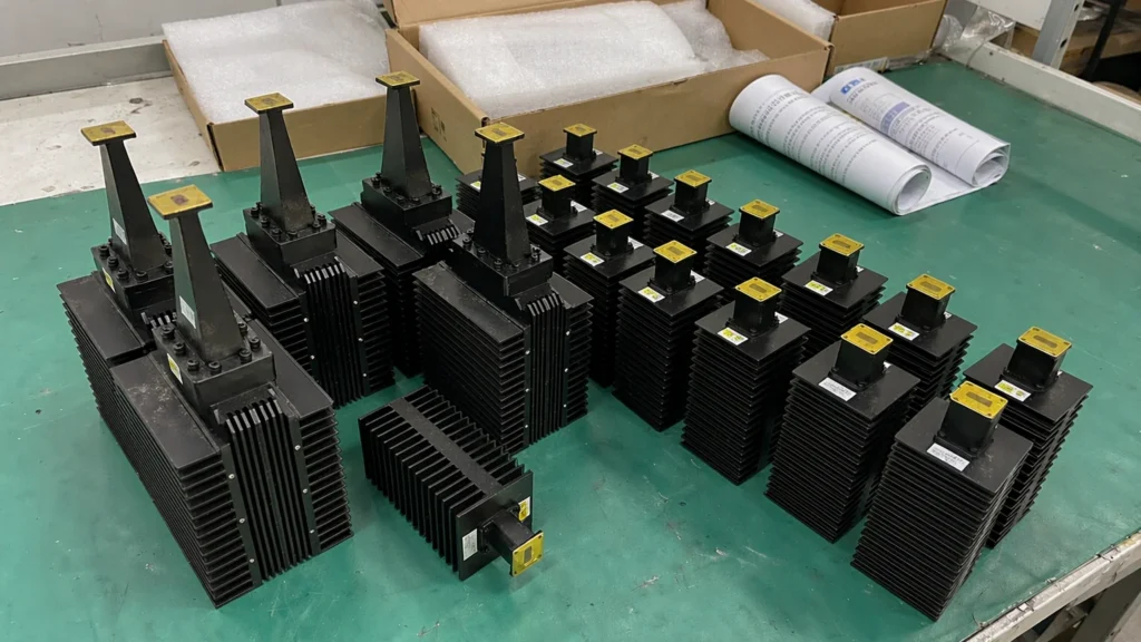
Dolph Microwave finished production 4.5 Meter Turning Head Antenna and test of Ext. Ka-band Tx27.5 to 31.0 GHz, Rx17.7-21.2GHz satcom antenna with 4 port Circular Pol. Axis Ratio 0.6dB. Product & Pedestal Features:  Wide variety of feed options designed to meet the latest international standards. S, C, X, Ku, DBS and Ka Band, Tx/Rx, 2Tx/2Rx, TT&C,

[Dolph Microwave] 4.5 Meter Turning Head Antenna with Ext.Ka-band Tx27.5 to 31.0 GHz, Rx17.7-21.2GHz Read More »

Curved Waveguide Types

Curved Waveguide Types

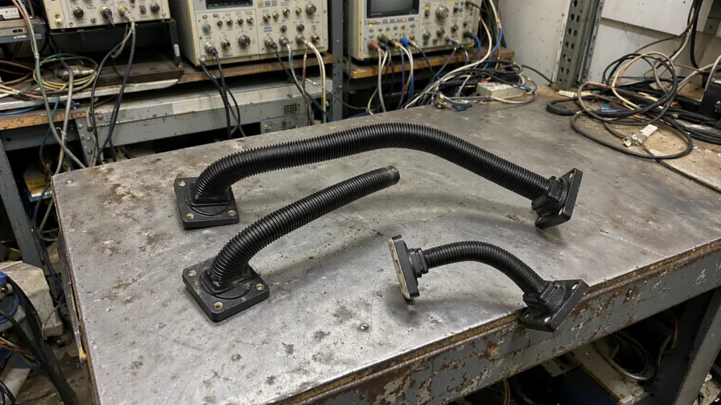
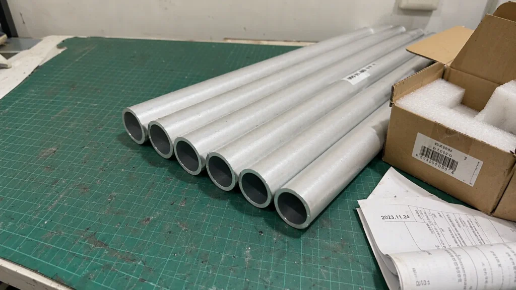
There are two types of curved waveguides: E-surface curved and H-surface curved. The curved waveguides include arc-shaped curved waveguides and cut-angle curved waveguides. Cut-angle curved waveguides can be used in situations where the arm length is short, the waveguide is large, the bandwidth is narrow, and the power is low. The standard bending angle is 90°,

Curved Waveguide Types Read More »

C-band Antenna Feeds & RF Networks from Dolph Microwave

C-band Antenna Feeds & RF Networks from Dolph Microwave

Antenna feeds and RF networks as the heart of antenna system from Dolph Microwave is R&D by experienced our engineers who engaged into satcom and RF field for years. The components can be offered including OMT, duplixer, filter, phase shifter and feedhorn etc. covering different bands like C-band, Ku-band, Ka-band, S-band. X-band and required dual band etc. Our

C-band Antenna Feeds & RF Networks from Dolph Microwave Read More »

【Standard Gain Horn Antenna】WR90 15dB SMA

【Standard Gain Horn Antenna】WR90 15dB SMA, Standard Gain Horn Antenna

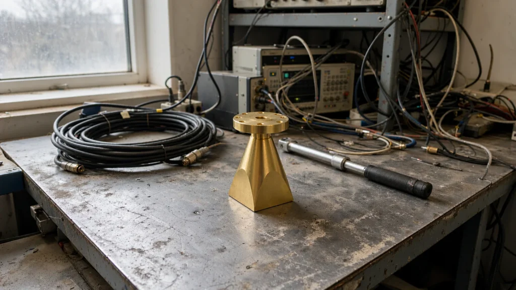
Dolph Microwave manufactures standard gain horn antennas specifically designs for utilization in emissions and immunity testing over the frequency range of 0.32 to 110 GHz. And, they offer high power handling capability, and low loss, also high directivity, and near constant electrical performance across a wide bandwidth, low gain variation across their operating frequency. In

【Standard Gain Horn Antenna】WR90 15dB SMA, Standard Gain Horn Antenna Read More »

[WR-340 Waveguide to Coaxial Adapters] WR-340 to SMA Female

[WR-340 Waveguide to Coaxial Adapters] WR-340 to SMA Female Waveguide to Coax Adapter UDR Cover Standard with 2.17 GHz to 3.3 GHz S Band in Aluminum

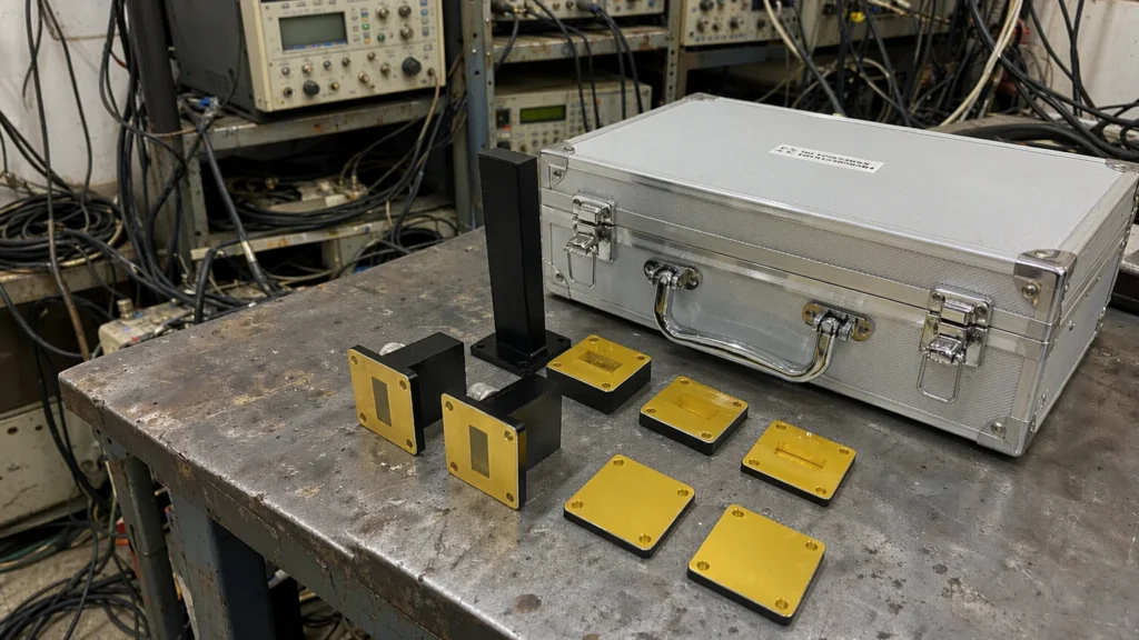
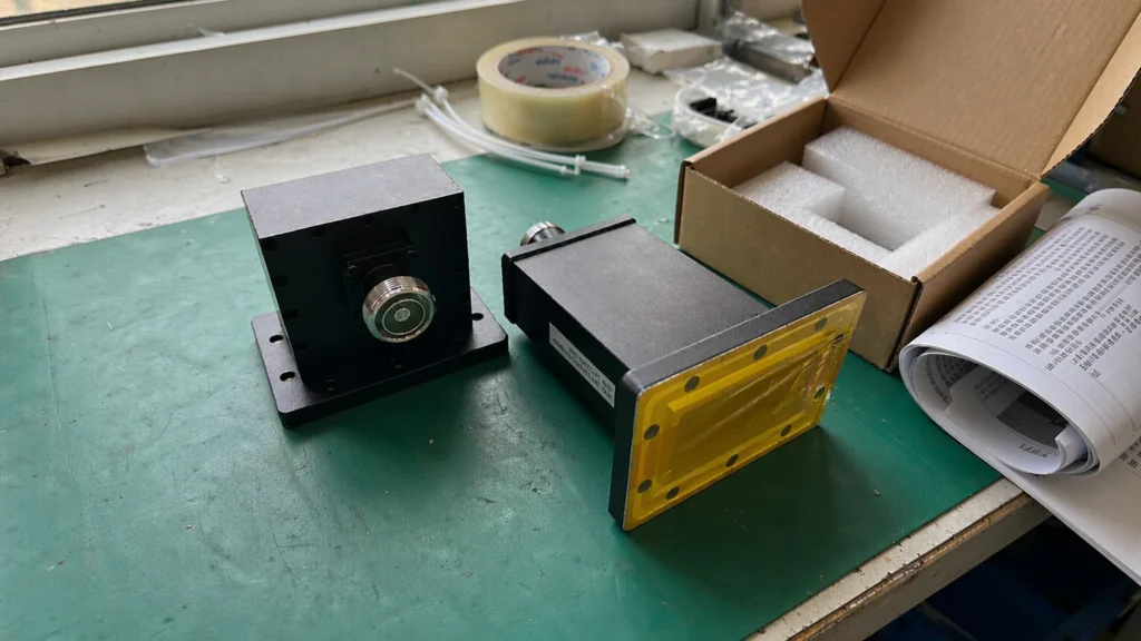
Dolph Microwave waveguide to coaxial adapter (also known as a waveguide coaxial transition) is manufactured with a right angle design. Right angle waveguide to coaxial adapter / transition has a waveguide size of WR-340 and UDR cover flange. This WR-340 waveguide to coax adapter / transition is constructed with a SMA coaxial connector that is

[WR-340 Waveguide to Coaxial Adapters] WR-340 to SMA Female Waveguide to Coax Adapter UDR Cover Standard with 2.17 GHz to 3.3 GHz S Band in Aluminum Read More »

What are the log-periodic antenna characteristics and performance results

What are the log-periodic antenna characteristics and performance results

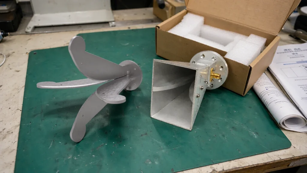
The log-periodic antenna is the main preferred form of the low-frequency UWB directional antenna. This antenna family has the remarkable capability to cover octave bandwidth or even UWB bandwidth of nearly 100 octaves. With a potential gain of up to 9 dB, it offers a significant boost to signal reception and transmission. At ultra-low frequencies,

What are the log-periodic antenna characteristics and performance results Read More »

What are the corresponding circular waveguide diameters for each frequency band

What are the corresponding circular waveguide diameters for each frequency band

A circular waveguide refers to a waveguide with a circular cross-section. The lowest order propagation mode in a circular waveguide is TE11, which provides minimal signal degradation.The possible TM modes in circular waveguides are TM01, TM02, TM11, and TM12. The modes maintained by circular waveguides have many similarities with those of rectangular waveguides. For example,

What are the corresponding circular waveguide diameters for each frequency band Read More »

【Rectangular to Circular WG Adapter】WG Transition (TE10-TE11) – S-band Rectangular to Circular Adapter

【Rectangular to Circular WG Adapter】WG Transition (TE10-TE11) – S-band Rectangular to Circular Adapter

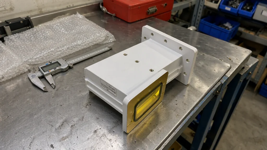
WR284 Rectangular to Circular WG Transition (TE10-TE11) Adapter is suitable for S-Band Magnetron Transition Adapter. Technical parameters are as below: Model: DH-32RCA71.42 Waveguide Size:R32 / WR284 Frequency: 2.850 GHz – 3.005 GHz Insertion Loss:< 0.05 dB Return Loss:>26dB Power Handling:Up to 5 MW Flanges:Customer TBS Material:Aluminium Finish:Conductive Oxidation Operating Pressure:3 bar absolut Operating Temperature:-20°C to

【Rectangular to Circular WG Adapter】WG Transition (TE10-TE11) – S-band Rectangular to Circular Adapter Read More »

[WG Mode Converter/Antenna] WR340 Mode Converter/Antenna for Microwave Plasma CVD Application

[WG Mode Converter/Antenna] WR340 Mode Converter/Antenna for Microwave Plasma CVD Application

If you have a microwave source of 2.45GHz, want to concentrate microwave energy in a chamber using Antenna. Then WR340 WG Mode Converter/Antenna must be what you need. WR340 WG Mode Converter/Antenna for microwave plasma CVD application. Model:DH-26WGMCTE10/TM01 (WR340) Frequency Range:2450±50 MHz VSWR (Max.):≤1.2:1 Handling Power:6 KW, CW Mode Converter:TE10-TM01 Water Flow:3-5 L/min Waveguide Type:WR340

[WG Mode Converter/Antenna] WR340 Mode Converter/Antenna for Microwave Plasma CVD Application Read More »

Scroll to Top
Blank Form (#3)