Author name: Dolph

Aluminum vs copper waveguide | 7 performance differences compared

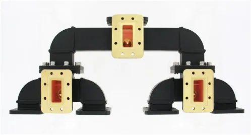
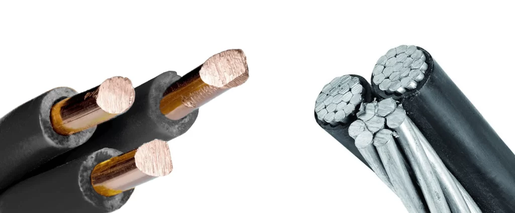
Aluminum waveguides offer 30-40% weight reduction and 5-15% cost savings versus copper, but with 20-30% higher signal loss above 18 GHz. Copper provides superior conductivity (100% IACS vs aluminum’s 61%), reducing attenuation by 0.5-2 dB/meter in high-frequency applications. Aluminum’s oxidation resistance lowers maintenance, while copper’s solderability simplifies assembly. For mmWave systems (24-100 GHz), copper’s performance […]

Aluminum vs copper waveguide | 7 performance differences compared Read More »

Flexible waveguide price factors | 5 cost drivers explained

Flexible waveguide pricing depends on material (PTFE vs. metallic alloys, ±15-30% cost variance), frequency range (higher frequencies increase cost by 20-40%), customization (bespoke designs add 25-50%), production volume (bulk orders reduce unit cost by 10-25%), and coating requirements (e.g., gold plating adds $50-200 per unit). Lead times under 4 weeks may incur rush fees. ​​Material

Flexible waveguide price factors | 5 cost drivers explained Read More »

Conical waveguide benefits | 4 technical advantages

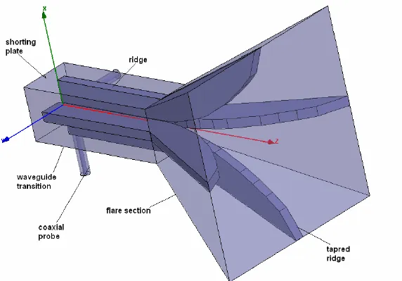
Conical waveguides offer broadband performance (e.g., 2:1 frequency ratio), low VSWR (<1.2:1), smooth mode transitions (reducing reflections by 20–30 dB), and flexible polarization handling (supporting TE/TM modes). Their tapered design minimizes impedance mismatch, making them ideal for feeds in parabolic antennas and radar systems. ​​Wider Frequency Coverage​ Conical waveguides outperform traditional rectangular or circular waveguides

Conical waveguide benefits | 4 technical advantages Read More »

How to choose rectangular waveguide sizes | 5 key factors

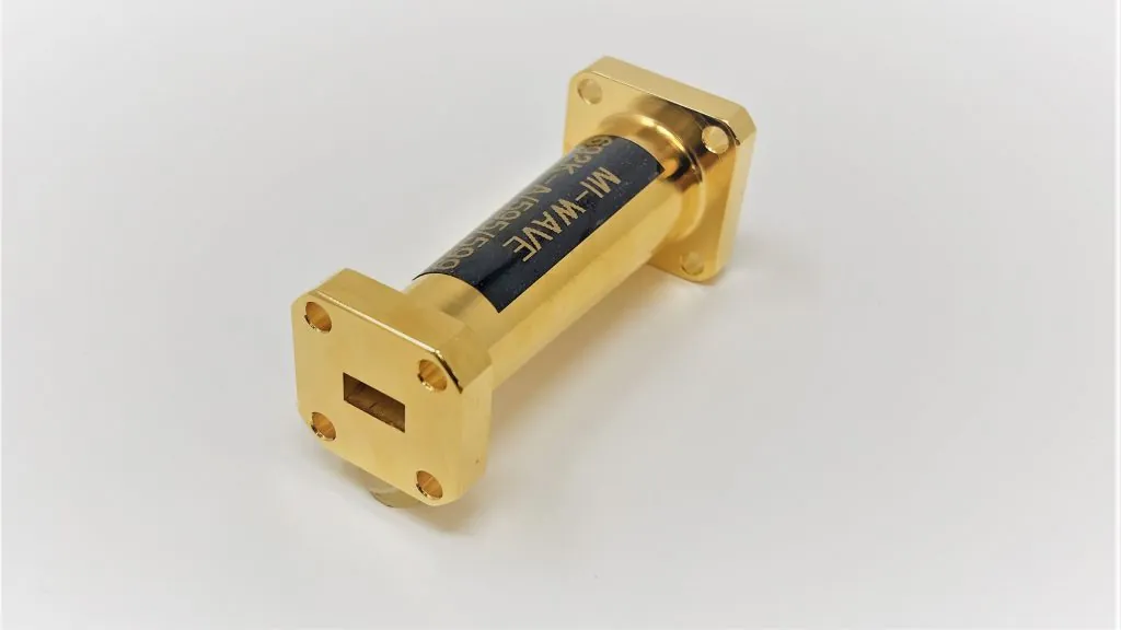
When selecting a rectangular waveguide size, consider the operating frequency (e.g., WR-90 for 8.2–12.4 GHz), cutoff frequency (ensure it’s 25–30% below the operating frequency), power handling (e.g., WR-112 handles 1.5 MW at 2.45 GHz), attenuation (lower for longer runs, like 0.1 dB/m in WR-62), and mechanical constraints (e.g., WR-430’s 4.3×2.15″ size for high power). Match

How to choose rectangular waveguide sizes | 5 key factors Read More »

Antenna Couplers vs Splitters | 3 differences explained

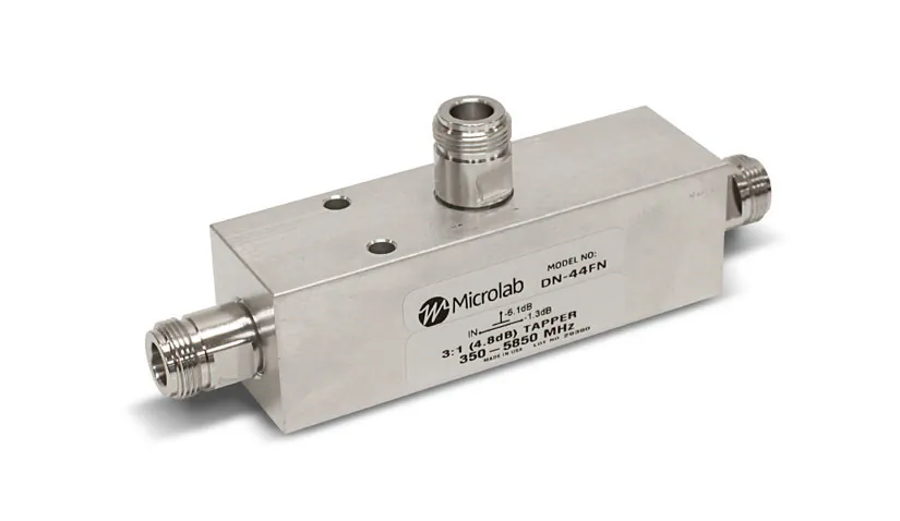
​Antenna couplers ​​preserve signal strength​​ with ​​<1dB insertion loss​​, while splitters ​​divide power evenly​​, causing ​​3–6dB loss per output port​​. Couplers ​​isolate ports (30–40dB isolation)​​ to prevent interference, whereas splitters have ​​minimal isolation (10–20dB)​​, risking ​​cross-talk in multi-device setups​​. Frequency range differs—couplers handle ​​0.5–40GHz with ±0.5dB flatness​​, but splitters typically support ​​0.1–6GHz with ±2dB variance​​.

Antenna Couplers vs Splitters | 3 differences explained Read More »

Phased Array Antenna manufacturers | top 5 guide

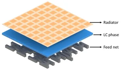
The global phased array antenna market is dominated by key players like Raytheon Technologies (30% market share), specializing in military-grade systems with 90° beam steering. Lockheed Martin’s AESA radars achieve 360° coverage with <1ms response time. Qorvo leads in 5G applications, producing compact 28GHz arrays with 256 elements. Huawei’s mMIMO antennas support 64T64R configurations for

Phased Array Antenna manufacturers | top 5 guide Read More »

Waveguide Magic Tee installation | 5 step process

​Installing a waveguide Magic Tee requires precision: first, align the E-arm and H-arm ports within 0.002″ tolerance using laser alignment tools. Secure flange connections with torque-controlled wrenches (12-15 lb-ft for standard WR-90 waveguides). Apply conductive epoxy (0.1mm thickness) at joints to maintain VSWR below 1.25:1. Test isolation between collinear ports (should exceed 30dB at 8-12GHz

Waveguide Magic Tee installation | 5 step process Read More »

Custom vs Standard Antennas | 4 key contrasts

Custom antennas are ​​tailored for specific applications​​, offering ​​optimized gain (3–5dB higher than standard)​​ and ​​precise frequency matching (±1% tolerance)​​, while ​​off-the-shelf antennas​​ provide ​​general-purpose performance (±5% frequency variance)​​ at ​​40–60% lower cost​​. Custom designs accommodate ​​unique form factors​​ (e.g., conformal aerospace shapes) with ​​IP67+ environmental protection​​, whereas standard antennas are limited to ​​mass-produced sizes

Custom vs Standard Antennas | 4 key contrasts Read More »

Flexible Waveguide types | 3 differences comparison

Flexible Waveguide types | 3 differences comparison

Flexible waveguides vary primarily in ​​material composition​​, ​​frequency range​​, and ​​bend radius tolerance​​. ​​Corrugated copper waveguides​​ offer ​​low loss (0.1–0.3 dB/m) for 5–110 GHz​​ but require ​​≥10x diameter bend radius​​, while ​​polymer-coated helical waveguides​​ allow ​​tighter bends (3x diameter)​​ with ​​higher attenuation (0.5–1.2 dB/m)​​. ​​Dielectric-core flexible waveguides​​ support ​​26.5–40 GHz​​ with ​​0.4 dB/m loss​​ but

Flexible Waveguide types | 3 differences comparison Read More »

Antenna Solutions for small spaces | 5 product picks

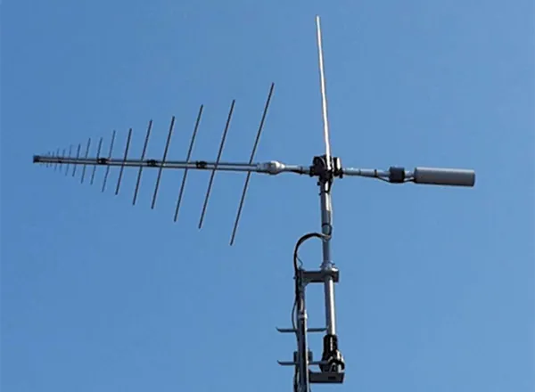
For space-constrained installations, compact antenna solutions include microstrip patch antennas (2.4GHz models as thin as 1.6mm), flexible printed antennas with 3mm bend radius for curved surfaces, and dielectric resonator antennas offering 8dBi gain in 30mm cubes. Foldable Yagi-Uda designs collapse to 15cm lengths while maintaining 12dBi gain at 5GHz. For IoT applications, chip antennas like

Antenna Solutions for small spaces | 5 product picks Read More »

Scroll to Top
Blank Form (#3)